Light emitting device

a technology of light-emitting devices and light-emitting components, which is applied in the association of printed circuit non-printed electric components, lighting and heating apparatuses, display means, etc., can solve problems such as unsatisfactory color rendering effects, and achieve the effect of excellent color rendering index

Inactive Publication Date: 2005-06-02
LEE KUN CHUI +2
View PDF7 Cites 143 Cited by
  • Summary
  • Abstract
  • Description
  • Claims
  • Application Information

AI Technical Summary

Benefits of technology

[0013] and a phosphor 50 is for absorbing lights having different wavelengths and emitted by the first and second light sources A and B, and is excited to emit a light 60 having a wavelength distinct from those of the first and second light sources A and b; wherein, the distinct light 60 is blended with the red light emitted from the third light source R and the lights emitted from the first and second light sources A and B, and a blended light is released to obtain a white light W having an excellent color rendering index.

Problems solved by technology

A reason behind is that, the “white light” defined by blending the light having a larger wavelength emitted by the phosphor excited by the blue light with the unexcited blue light, when compared with natural sunlight, has unsatisfactory color rendering effects.

Method used


Image

  • Light emitting device
  • Light emitting device
  • Light emitting device

Examples


Embodiment Construction

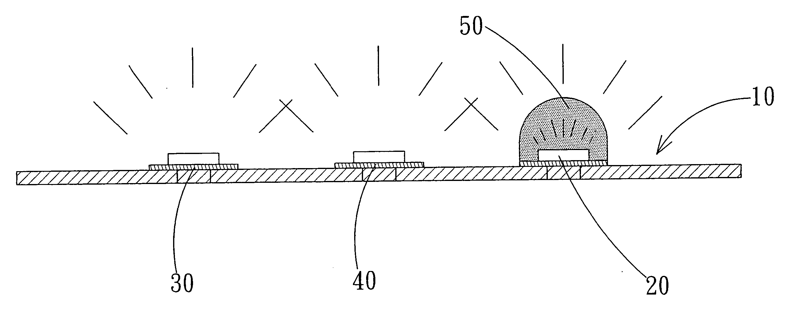
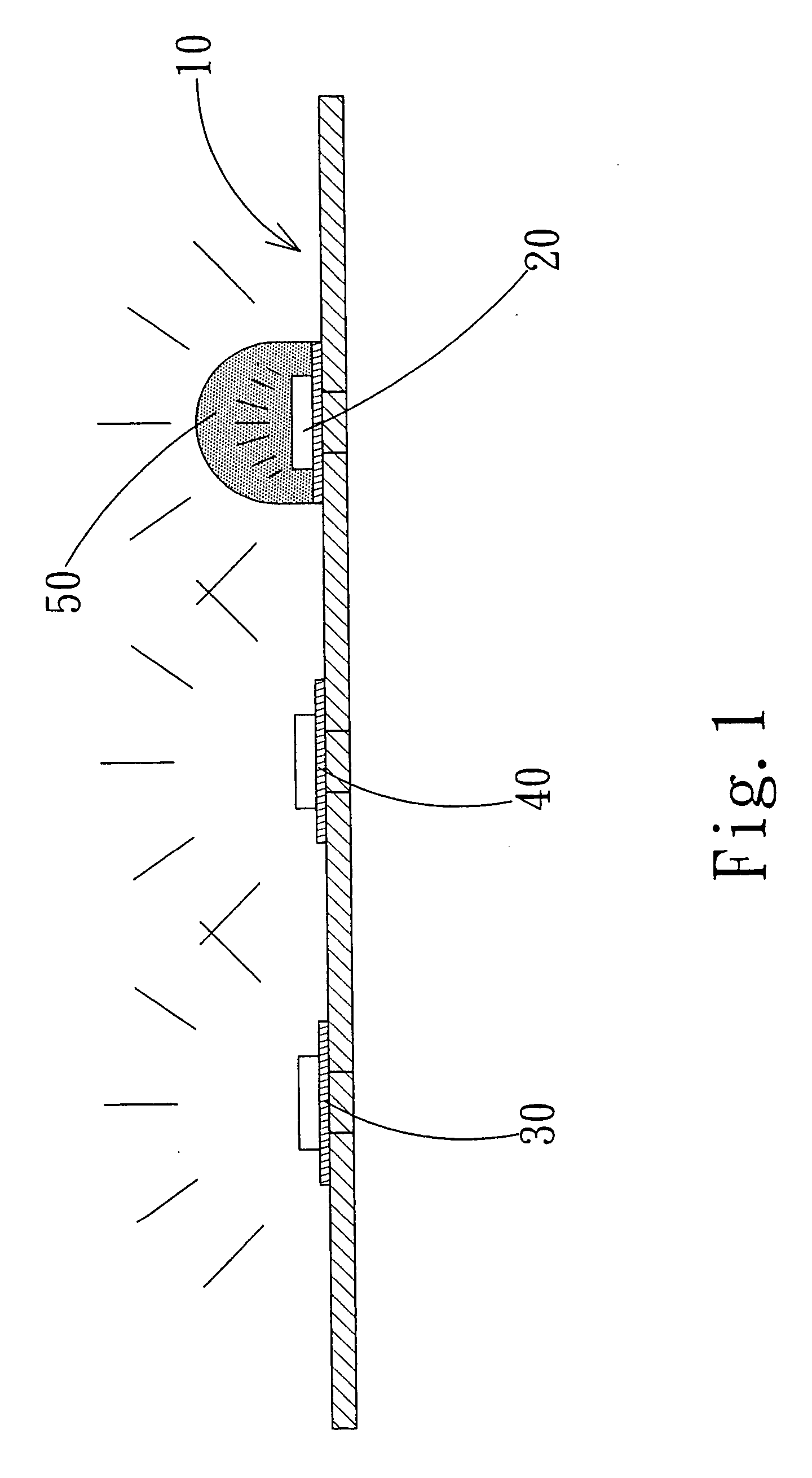
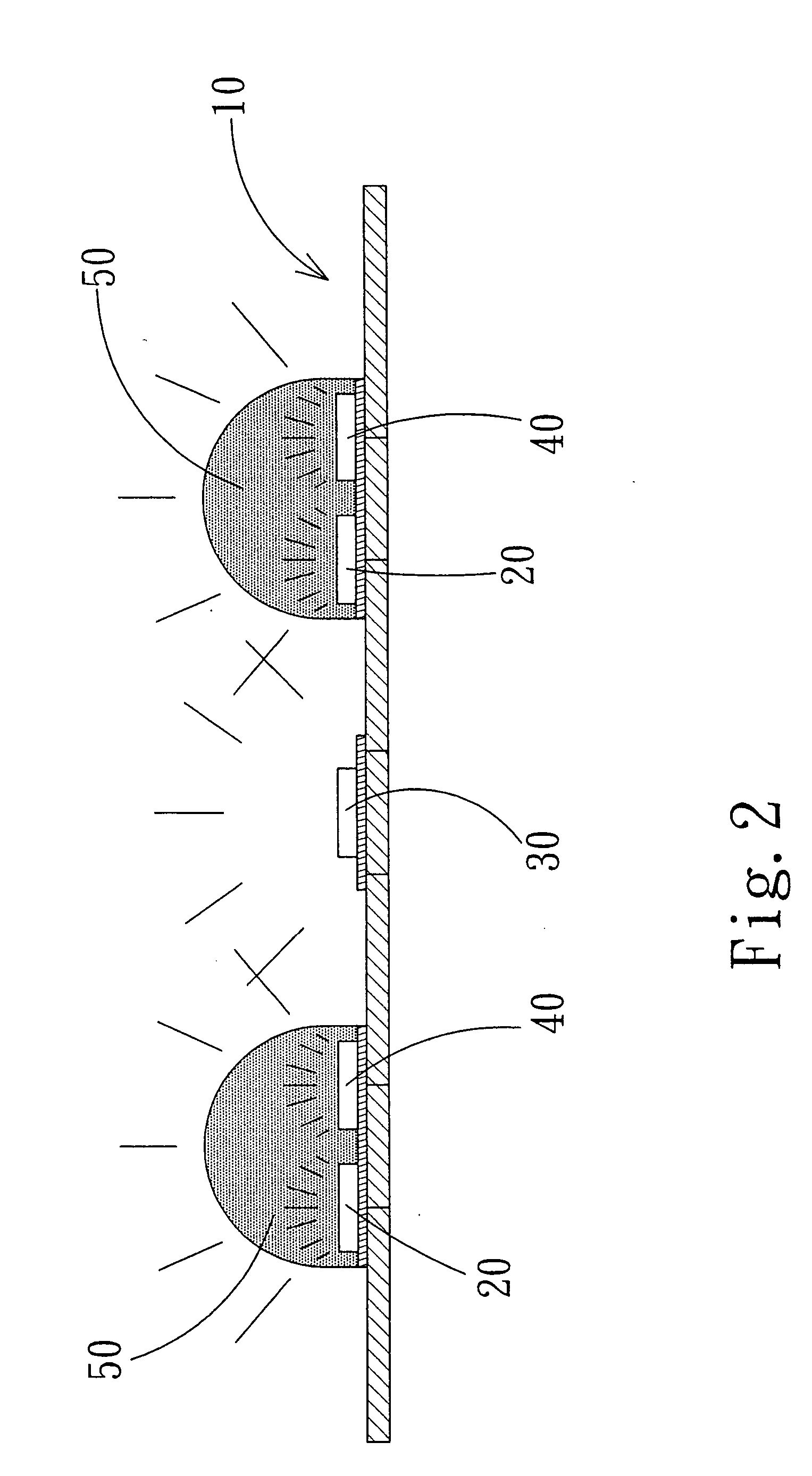
[0033] Referring to FIGS. 1 and 6, a device may include a PCB or other modularized base. Conducting pins 22, 32 and 42 of the first LED 20, the second LED 30 and the third LED 40 are soldered to the device 10 to form an electric loop. The third LED 40 is located between the first and second LEDs 20 and 30. The phosphor 50 is formed by mixing transparent resin and phosphor powder, and is encapsulated around the first LED 20. When being triggered by an electrode, the first LED 20 emits a blue light having a wavelength ranging between 360 nm and 480 nm for serving as a first light source A. When being triggered by an electrode, the second LED 30 emits a blue to green light defined by naked eye and having a wavelength ranging between 480 nm and 570 nm for serving as a second light source B. When being triggered by an electrode, the third LED 40 emits a red light having a wavelength ranging between 585 nm and 780 nm for serving as a third light source R. Referring to FIG. 5, the phosphor...


PUM

PropertyMeasurementUnit
wavelength rangingaaaaaaaaaa

Abstract

A light emitting device includes at least three light emitting source and a phosphor, with the three light sources consisted of following light emitting diodes (LED) emitting lights having different wavelengths. Wherein, two light sources are used to excite the phosphor to produce a distinct wavelength different from those of the two light sources. The distinct wavelength is blended with portions of the two light sources and a light source from another independent light source, and a blended light is released to obtain a white light having an excellent color rendering index.

Description

BACKGROUND OF THE INVENTION [0001] (a) Field of the Invention [0002] The invention relates to a light emitting device, and more particularly, to a light emitting device comprising three light emitting diodes (LED) and a phosphor. The phosphor is excited by absorbing lights from first and second light sources to emit a distinct light. The distinct light is blended with a red light from the third light source and unexcited blue lights from the first and second light sources, and a blended light is released to obtain a white light having an excellent color rendering index. [0003] (b) Description of the Prior Art [0004] With reference to FIG. 8 showing a curve diagram of natural sunlight (natural white light), a light wavelength of the light therein ranges between 360 and 750 nm. [0005] To manufacture a white light emitting device having a wavelength approaching that of natural sunlight (white light), the Taiwan Patent Publication No. 383508 discloses a light emitting device and a displ...

Claims


Application Information

Patent Timeline
Patent Type & Authority Applications(United States)
IPC IPC(8): C09K11/02F21V9/00H01L25/075H01L33/48H01L33/50H05K1/18
CPCH01L25/0753Y10S362/80H01L33/50H01L2924/0002H01L2924/00
Inventor LEE, KUN-CHUICHENG, TZU-CHICHENG, JUNG-PIN
Owner LEE KUN CHUI
Why Eureka
Try Eureka