Mult- purpose end-mill

a technology of end-mill and slot, which is applied in the direction of shaping cutter, manufacturing tools, transportation and packaging, etc., can solve the problems of minor accuracy loss, time-consuming, and general unsuitability of end-mill configured for rough machining

Inactive Publication Date: 2005-06-02
HANITA METAL WORKS
View PDF9 Cites 18 Cited by
  • Summary
  • Abstract
  • Description
  • Claims
  • Application Information

AI Technical Summary

Benefits of technology

[0012] It is therefore one of the objects of the present invention to obviate the disadvantages of prior art cutting tools and to provide ...

Problems solved by technology

End-mills configured for rough machining are generally unsuitable for finish machining.
The smaller core diameter may lead to minor loss of accuracy due to tool bending under pressure, but this is of little moment for roughing operations.
This is tiresome when done by hand, and still time consuming even when carried out by an automatic machine.
This method however involves clamping and unclamping each workpiece, and aside from the time needed for this, there is greater risk of ina...

Method used


Image

  • Mult- purpose end-mill
  • Mult- purpose end-mill
  • Mult- purpose end-mill

Examples


Embodiment Construction

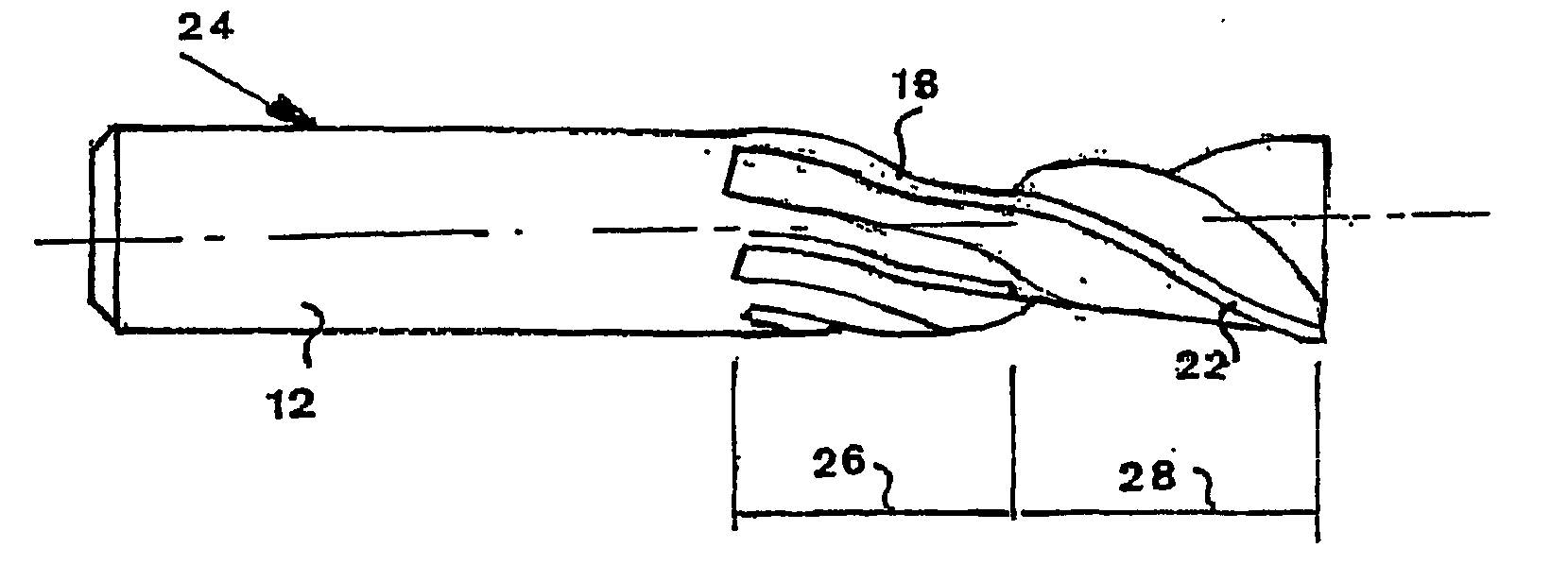
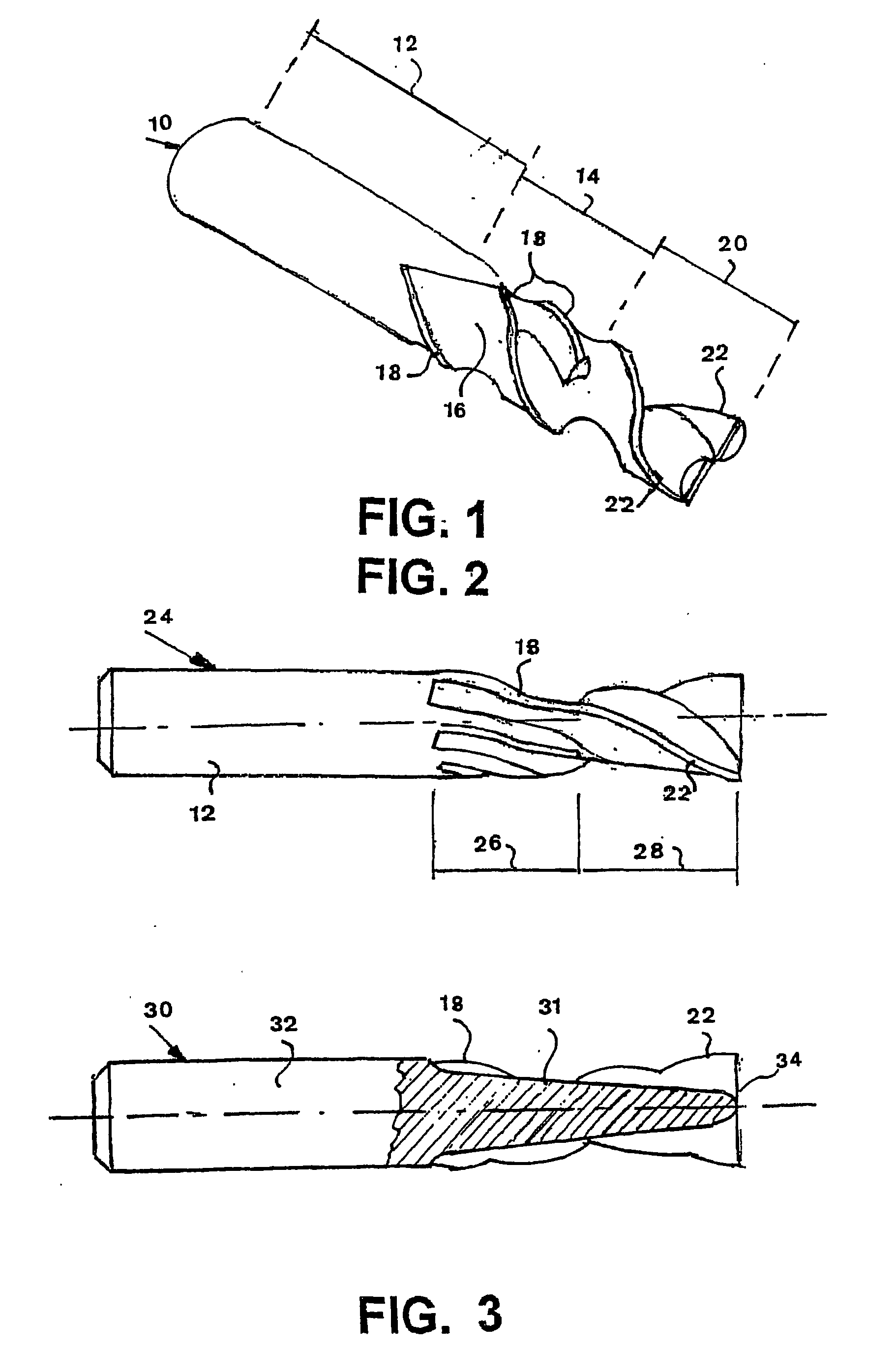
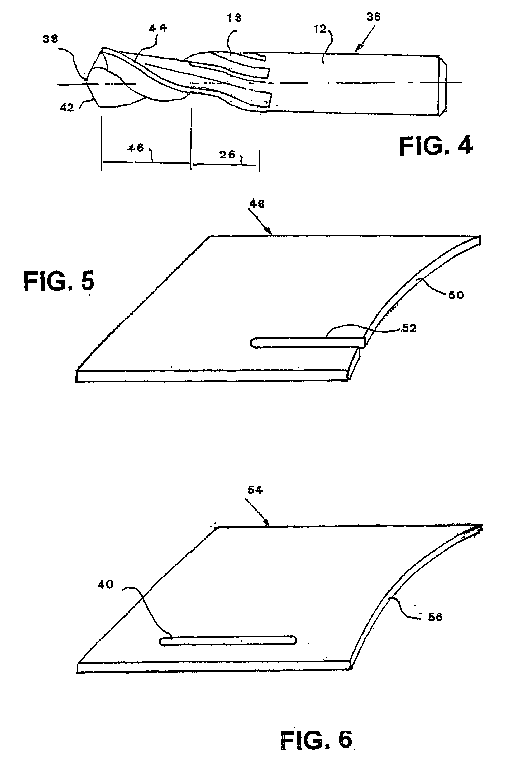
[0028] There is seen in FIG. 1 a multi-purpose end-mill 10 particularly useful for open contour machining, for example producing a workpiece of the type seen in FIG. 5. The end mill 10 is suitable for both rough machining and finish machining.

[0029] A cylindrical shank portion 12 is arranged to be gripped in a machine tool (not shown), such as a router or a milling machine, and in some types of work even a lathe or drilling machine.

[0030] The shank portion 12 is connected to a first cutting portion 14 comprising a core 16 supporting a plurality of spaced-apart cutting teeth 18 for a first type of machining.

[0031] The first cutting portion 14 is connected to a second cutting portion 20 provided with a plurality of spaced-apart cutting teeth 22 for a second type of machining.

[0032] Advantageously from considerations of core support diameter, the first type of machining is finishing, and the second type of machining is roughing. This is the arrangement in the shown embodiment. Howe...


PUM


Abstract

A multi-purpose end-mill to be used for different machining purposes, in particularly useful for closed or open contours machining. The end-mill comprises a cylindrical shank portion connected to a first cutting portion provided with a plurality of spaced-apart cutting teeth and a second portion provided with a plurality of different spaced-apart cutting teeth.

Description

FIELD AND BACKGROUND OF THE INVENTION [0001] The present invention relates to the machining of slots by use of a rotational cutting tool. More particularly, the invention provides an end mill, which can be used for different machining purposes by changing the distance between a thin workpiece and the end mill shank. This change is accomplished either by moving the workpiece or the cutter. [0002] A common requirement is to machine a slot, straight or contoured, in a thin workpiece. “Thin” means that the machined item is usually no thicker than the tool diameter. [0003] If the required slot reaches an outer edge of the workpiece, or the operation to be carried out comprises machining the outer edge, then the first operation is rough machining, leaving a little material for finishing, and the following operation is finish machining to the required size. [0004] End-mills configured for rough machining are generally unsuitable for finish machining. During rough machining much material is...

Claims


Application Information

Patent Timeline
IPC IPC(8): B23B51/08B23C5/10
CPCB23B51/08B23C5/10B23C2210/0492B23C2210/203B23C2210/285Y10T407/1946B23C2220/605Y10T407/1952Y10T408/348Y10T407/196B23C2210/405
Inventor DOV, AVIVOLOKH, VLADIMIR
Owner HANITA METAL WORKS
Why Eureka
Try Eureka