
Method and system for computer network implemented vehicle diagnostics

Inactive Publication Date: 2005-06-02
INNOVA ELECTRONICS
View PDF0 Cites 54 Cited by
  • Summary
  • Abstract
  • Description
  • Claims
  • Application Information

AI Technical Summary

Problems solved by technology

The diagnostic trouble code signals are related to a problem status of the vehicle.

Method used


Image

  • Method and system for computer network implemented vehicle diagnostics
  • Method and system for computer network implemented vehicle diagnostics
  • Method and system for computer network implemented vehicle diagnostics

Examples


Embodiment Construction

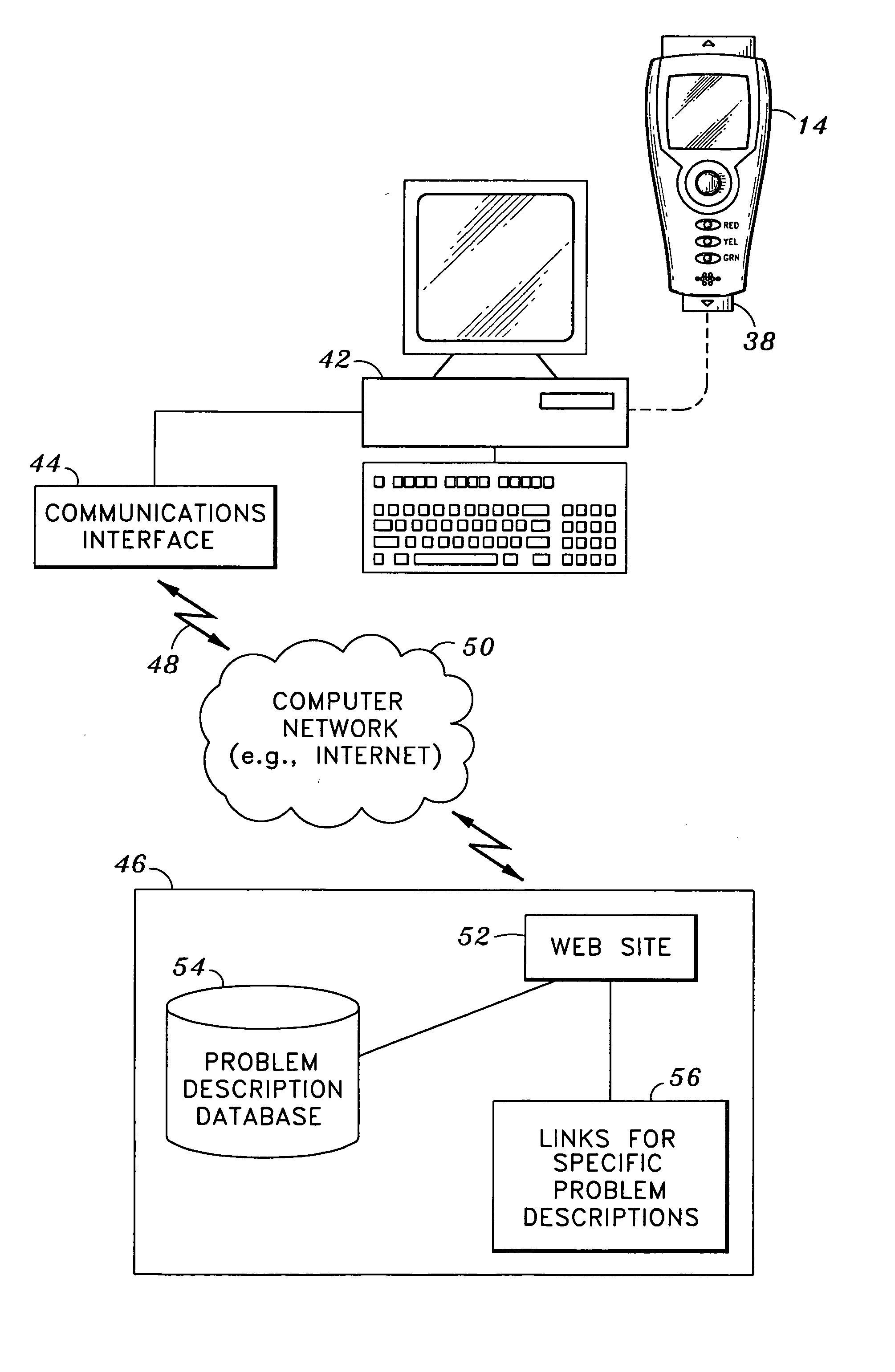
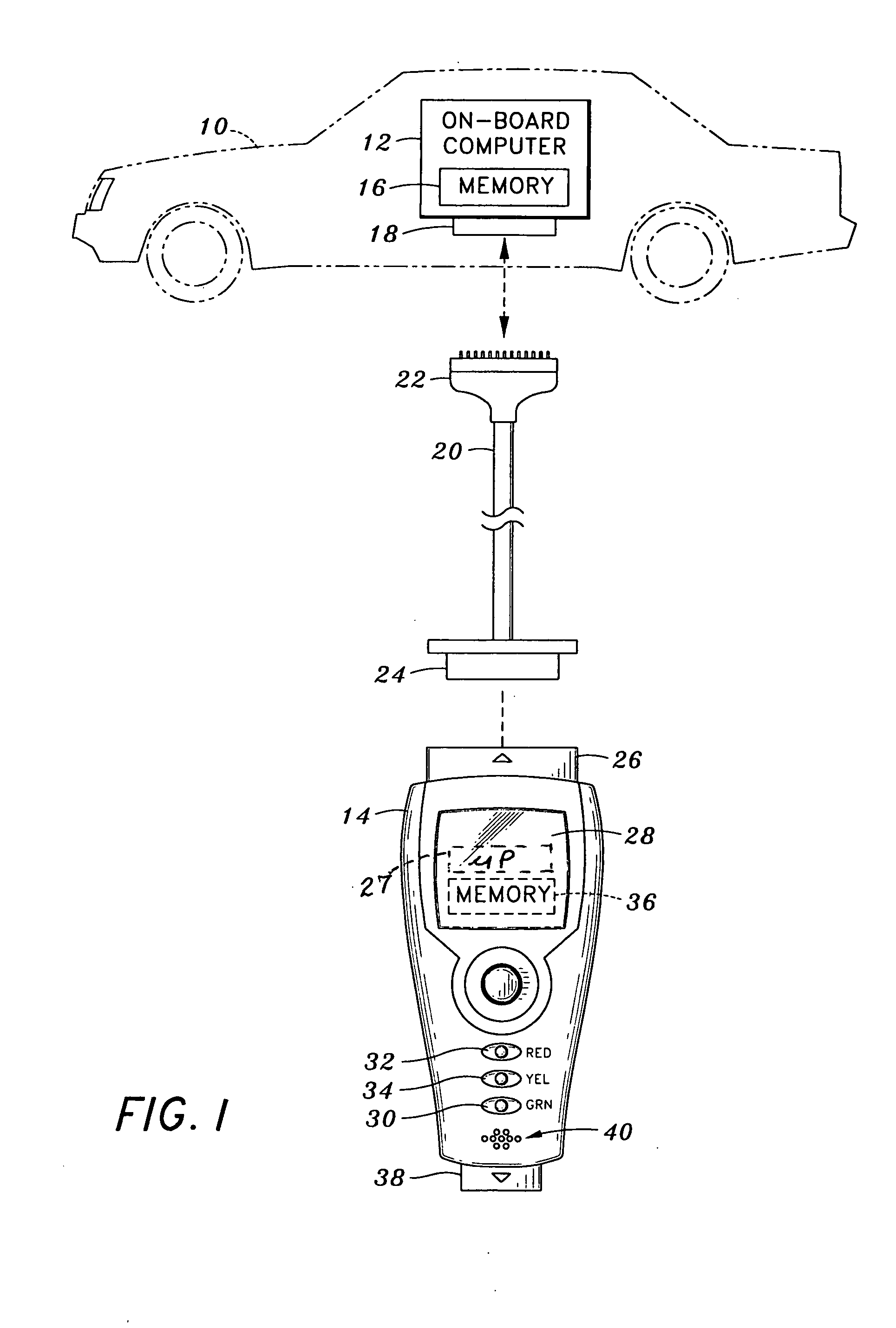
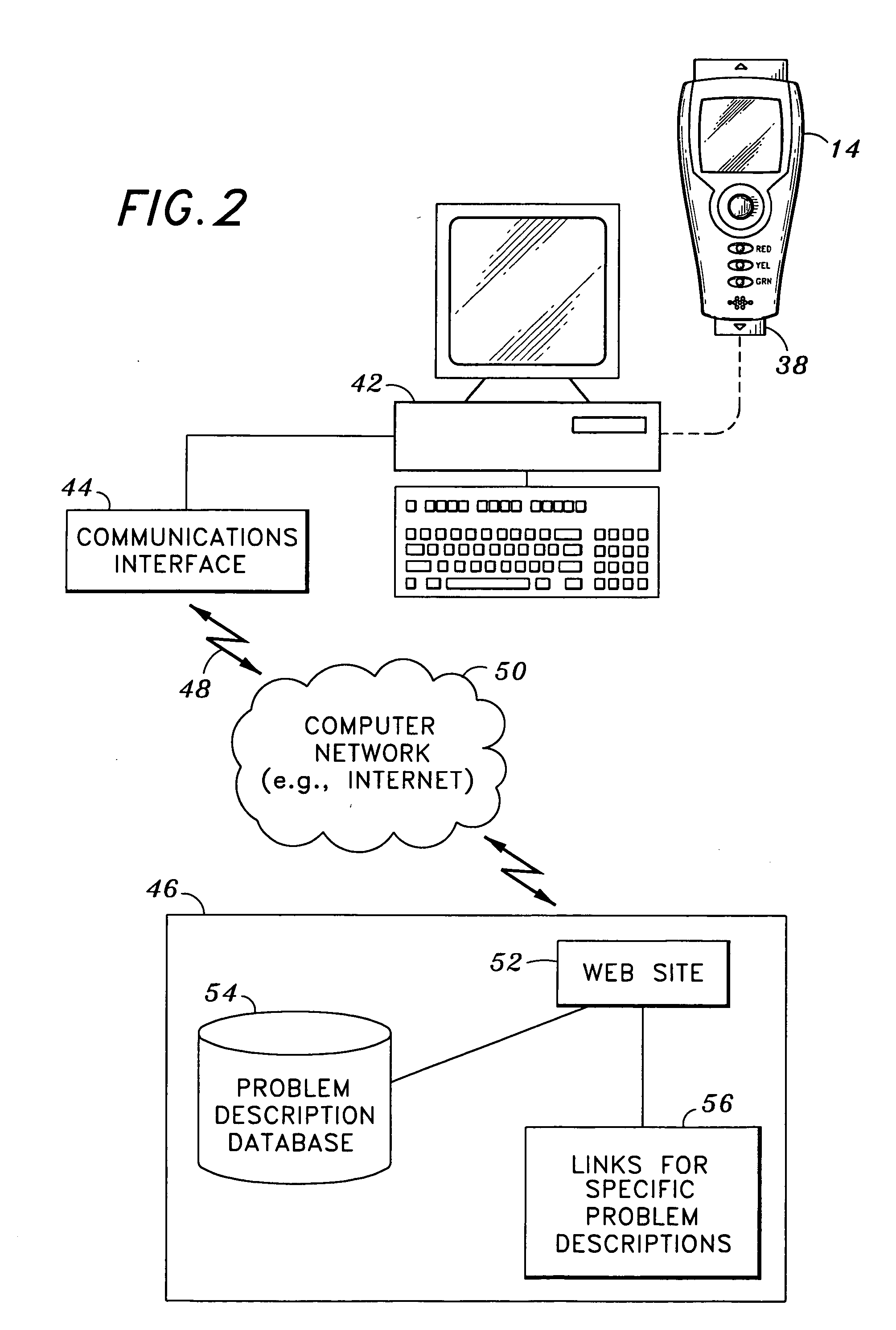
[0028] Referring now to the drawings wherein the showings are for purposes of illustrating a preferred embodiment of the present invention only, and not for purposes of limiting the same, FIGS. 1-7 illustrate methods and systems of diagnosing a vehicle 10 according to aspects of the present invention.

[0029] Referring now to FIG. 1 there is depicted the vehicle 10. The vehicle has an on-board computer 12. As will be discussed in detail below, the on-board computer 12 is configured to generate diagnostic trouble code signals for access by a code reader 14.

[0030] The on-board computer 12 includes a memory 16 The on-board computer 12 is contemplated to be a portion of a computer control system of the vehicle 10. In this regard, the computer control system further includes several related electronic control devices (sensors, switches, and actuators). The control devices may control various systems and / or subsystems within the vehicle 10. These electronic control devices send informatio...


PUM


Abstract

A method of diagnosing a status of a vehicle. The vehicle has an on-board computer for generating a diagnostic trouble code signal related to a passed or problem status of the vehicle. A portable code reader is connected to the on-board computer. Diagnostic trouble code signals are communicated from the on-board computer to the code reader. The code reader communicates to a personal computer respective ones of the diagnostic trouble code signals related to a problem status of the vehicle. The personal computer communicates the respective ones of the diagnostic trouble code signals from the personal computer to a remote computer. The remote computer is configured to correlate the diagnostic trouble code signals to problem description data for diagnosing the vehicle. Problem description data correlated to the respective ones of the diagnostic trouble code signals are communicated from the remote computer to the personal computer.

Description

CROSS-REFERENCE TO RELATED APPLICATIONS [0001] (Not Applicable) STATEMENT RE: FEDERALLY SPONSORED RESEARCH / DEVELOPMENT [0002] (Not Applicable) BACKGROUND OF THE INVENTION [0003] The present invention relates generally to methods and systems of diagnosing a vehicle, and more particularly to a method and system which contemplates establishing an electronic communications link with a remote computer for correlation of diagnostic fault codes. [0004] Modern motor vehicles include a computer control system. The main purpose of the vehicle's computer control system is to provide maximum engine performance with the least amount of air pollution and the best fuel efficiency possible. The computer control system consists of the on-board computer and several related electronic control devices (sensors, switches, and actuators). The control devices may control various systems and / or subsystems within the vehicle. These electronic control devices send information to the on-board computer about s...

Claims


Application Information

Patent Timeline
Patent Type & Authority Applications(United States)
IPC IPC(8): G06F19/00G07C5/00G07C5/08
CPCG06Q90/00G07C5/085G07C5/008
Inventor CHEN, IEON C.
Owner INNOVA ELECTRONICS
Learn More