Split scan line and combined data line x-ray detectors

a detector and scan line technology, applied in the field of x-ray imaging systems, can solve the problems of increasing cost and power consumption, doubling the readout electronics, and reducing reliability, so as to reduce the number of readout channels, increase detector read times, and reduce cost and power consumption

Active Publication Date: 2005-06-09
GE MEDICAL SYST GLOBAL TECH CO LLC
View PDF7 Cites 38 Cited by
  • Summary
  • Abstract
  • Description
  • Claims
  • Application Information

AI Technical Summary

Benefits of technology

[0011] The embodiments of the present invention provide several advantages. One such advantage that is provided by an embodiment of the present invention is the provision of a detector having split scan lines. Utilization of split scan lines increases detector read times, which reduces the number of readout channels. The reduction in the number of readout channels reduces cost and power consumption and simultaneously improves reliability of an x-ray detector.
[0012] Another advantage that is provided by an embodiment of the present invention is the provision of a detector having non-split data lines. A further advantage that is provided by another embodiment of the present invention is the provision of a detector having combined data lines. Utilization of non-split data lines and combined data lines can reduce the amount of readout electronics and provide the above stated advantages.
[0013] Moreover, the embodiments of the present invention are capable of supporting varying degrees of resolution through the ability of combining varying numbers of pixels that are read simultaneously and reducing the amount of time required to completely read a detector, thus increasing the acquisition frame rate when the resolution desired is less than the intrinsic resolution of the detector. This effectively allows an x-ray system to increase frame rate without compromising resolution, which increases application versatility for a particular detector design.

Problems solved by technology

However, twice the number of readout channels is required to support all of the data line segments, which increases costs and power consumption and decreases reliability.
Doubling the readout electronics increases power consumption of the detector and heat generated therein.
Increased heat generation results in increased costs in equipment to remove the heat.
Also, in designing readout circuitry, electronic noise performance is a concern.

Method used


Image

  • Split scan line and combined data line x-ray detectors
  • Split scan line and combined data line x-ray detectors
  • Split scan line and combined data line x-ray detectors

Examples


Embodiment Construction

[0020] In the following figures, the same reference numerals will be used to refer to the same components. While the present invention is described with respect to x-ray detectors, corresponding x-ray systems, and methods for operating each, the present invention is capable of being adapted for various purposes and is not limited to the following applications: computed tomography (CT) systems, radiotherapy or radiographic systems, x-ray imaging systems, and other applications known in the art. The present invention may be applied to radiographic detectors, cardiographic detectors, or other detectors known in the art.

[0021] In the following description, various operating parameters and components are described for one constructed embodiment. These specific parameters and components are included as examples and are not meant to be limiting.

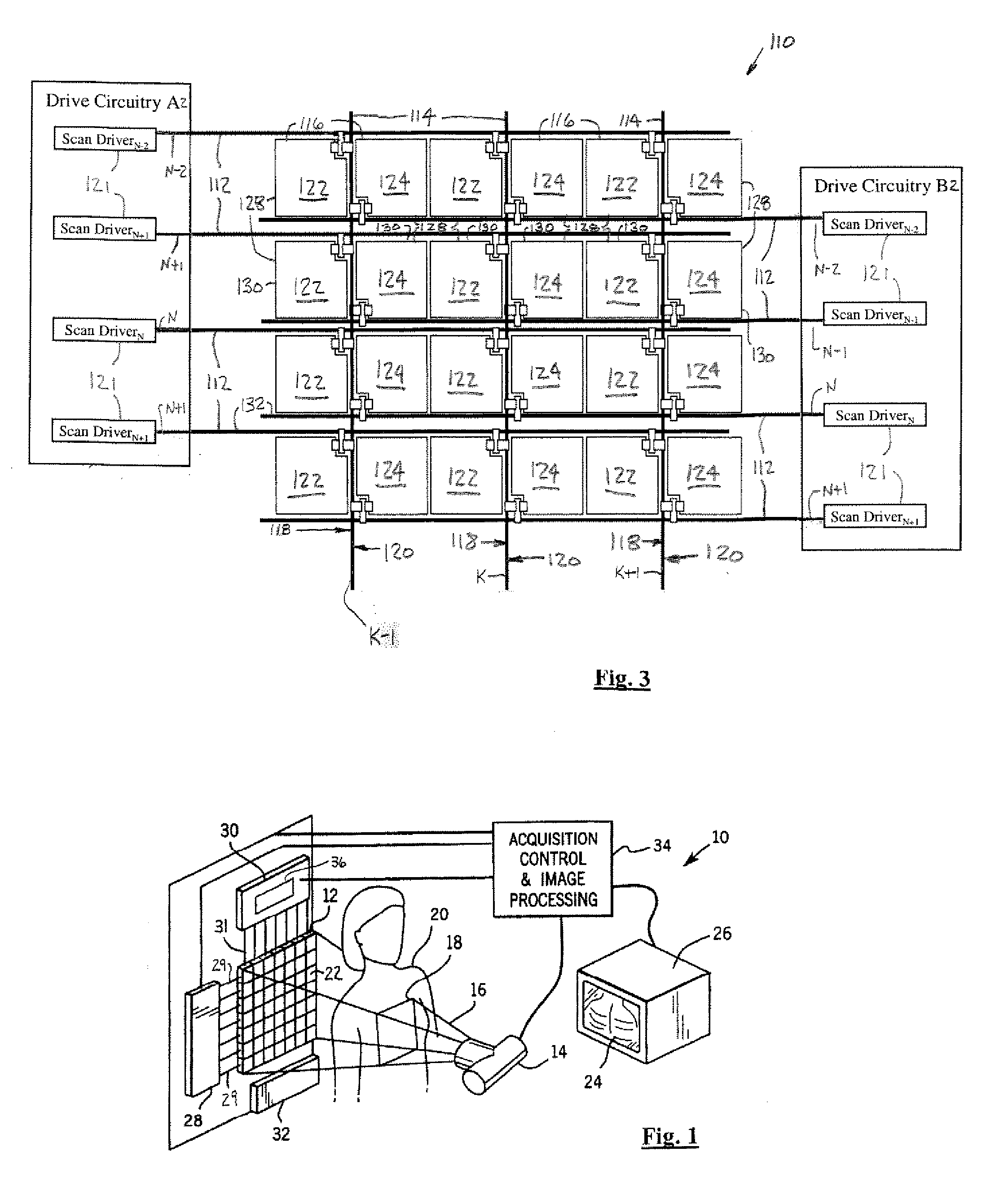
[0022] Referring now to FIG. 1, a perspective and block diagrammatic view of an x-ray imaging system 10 utilizing a detector array or x-ray detec...


PUM


Abstract

An x-ray detector (50) includes multiple pixels that receive x-rays. The x-ray detector (50) includes a split scan line (52) that activates the pixels and a data line (54) that conducts charge indicative of the x-rays.

Description

BACKGROUND OF INVENTION [0001] The present invention relates generally to x-ray imaging systems. More particularly, the present invention relates to improved x-ray detectors and methods of operating the same. [0002] An x-ray system typically includes an x-ray beam source and an x-ray detector. An x-ray beam is directed by the x-ray source across a region of interest of a patient and is detected by the x-ray detector, which in turn generates projection data in response to the x-ray beam. [0003] A solid-state x-ray detector commonly has an array of pixels composed of field effect transistors (FETs) that perform as switches and photodiodes, which detect light. The FETs and the photodiodes are constructed of amorphous silicon, over which cesium iodide (CsI) is deposited. The CsI absorbs the x-rays, generated by the x-ray beam source, and converts them into light energy, which is then detected by the photodiodes. The photodiodes, due to their construction, perform as capacitors and store...

Claims


Application Information

Patent Timeline
Patent Type & Authority Applications(United States)
IPC IPC(8): H01L27/14G01T1/20H04N5/32H04N5/357
CPCH04N5/335H04N5/32H04N25/00
Inventor PETRICK, SCOTT W.
Owner GE MEDICAL SYST GLOBAL TECH CO LLC
Why Eureka
Try Eureka