Rotor for rotary electric machine
a technology of rotating electric machines and rotating shafts, which is applied in the direction of dynamo-electric machines, magnetic circuit rotating parts, and shape/form/construction of magnetic circuits, etc. it can solve the problems of reducing the general magnetic flux amount, reducing the output torque, and the manufacturing step for staggering the magnets is rather complicated, so as to reduce the output torque and simplify the manufacturing step for staggering the magnets
- Summary
- Abstract
- Description
- Claims
- Application Information
AI Technical Summary
Benefits of technology
Problems solved by technology
Method used
Image
Examples
second embodiment
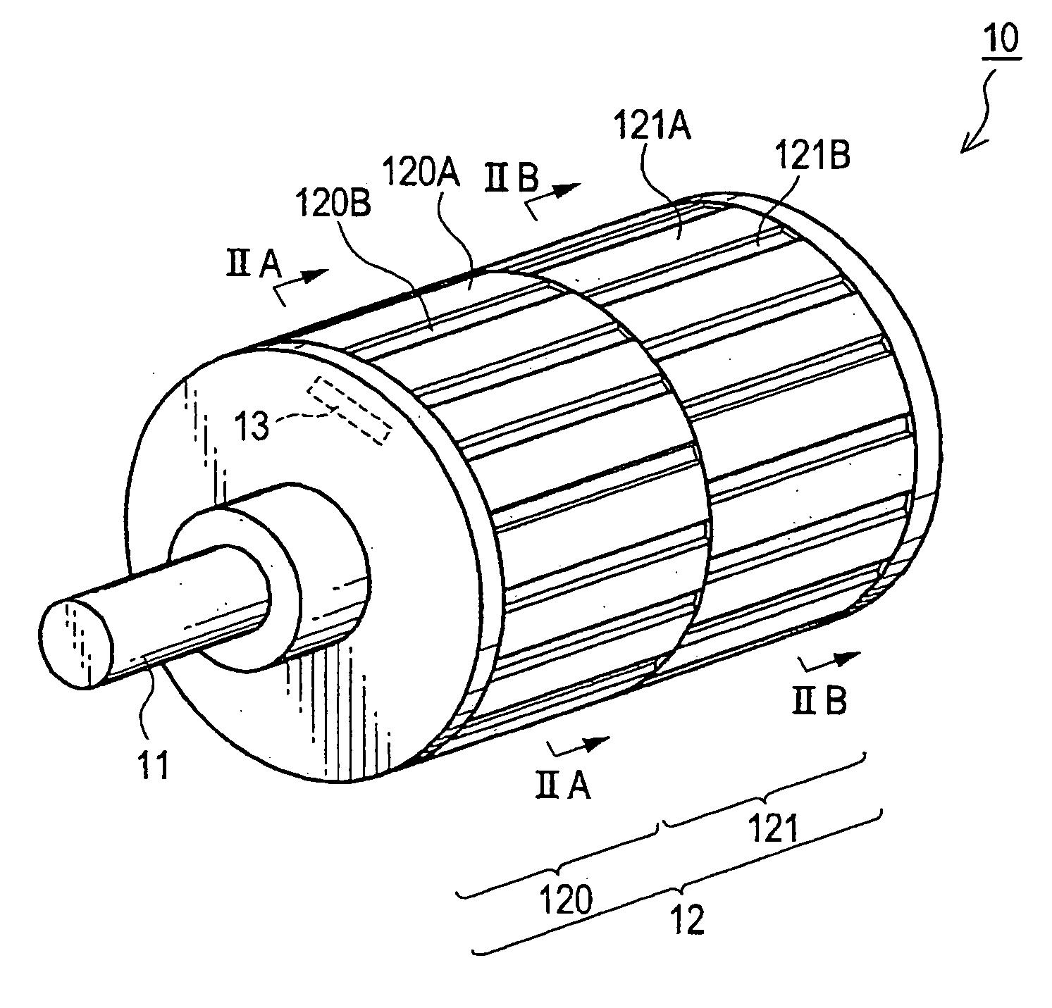
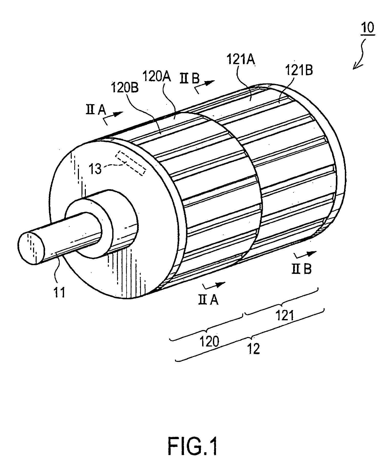
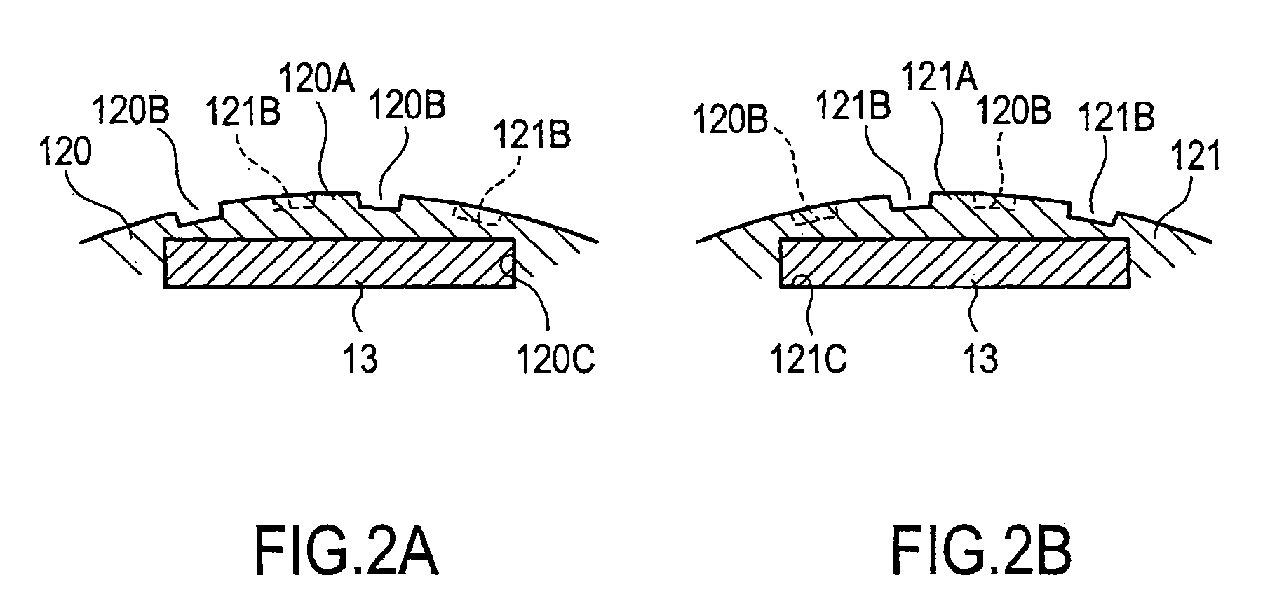
[0036] Referring to FIG. 7 and FIGS. 8A and 8B, this invention will be described. In this embodiment, no gaps are formed in the outer peripheral surface of the rotor 10. Instead, as shown in FIGS. 8A and 8B, through holes 122B are formed between an outer peripheral surface 122A of a first rotor core 122 and the permanent magnets 13, and through holes 123B are formed between an outer peripheral surface 123A of a second rotor core 123 and the permanent magnets 13. When seen through from the axial direction, the through holes 122B and 123B are arranged alternately at equal intervals.
[0037] In this embodiment also, it is possible to reduce cogging torque and torque ripple. Further, since no gaps are formed in the outer peripheral surface of the rotor 10, the outer peripheral surface can maintain a circular section, making it possible to prevent generation of noise during rotation or occurrence of energy loss due to air resistance.
[0038] In this embodiment also, rotor cores of the same ...
third embodiment
[0039] Next, referring to FIG. 9, this invention will be described. This embodiment employs two rotor cores 124 and two rotor cores 125, arranged alternately along the direction of the shaft 11 of the rotor 10 such that circumferential staggering of gaps 124B and 125B with respect to each other occurs at three or more axial positions. In this embodiment also, it is possible to use rotor cores of the same kind as the rotor cores 124 and 125, and arrange them axially in opposite directions, with the gap positions being circumferentially varied.
[0040] By thus arranging a number of small-sized rotor cores 124 and 125 along the shaft 11, it is possible to reduce the unbalance in weight.
fourth embodiment
[0041] Next, referring to FIG. 10, this invention will be described. In this embodiment, rotor cores 126, 127, 128, and 129 are used and arranged along the direction of the shaft 11, with their gaps 126B, 127B, 128C, and 129B being gradually staggered with respect to each other in their circumferential positions.
[0042] This makes it possible to adjust the cogging torque more accurately and to reduce in cogging torque and torque ripple. In this embodiment, it is possible for the rotor cores 126 through 129 can be of two kinds in view of the constructions thereof. In other words, two rotor cores are arranged oppositely in the axial direction to thereby form the rotor cores 126 and 129. Other two rotor cores are arranged oppositely in the axial direction to thereby form the rotor cores 127 and 128. Due to this construction, it is possible to keep the production cost for the rotor low. Further, while in this embodiment the gap positions are gradually staggered circumferentially, it is a...
PUM
 Abstract
Description
Claims
Application Information
 - R&D
- Intellectual Property
- Life Sciences
- Materials
- Tech Scout
- Unparalleled Data Quality
- Higher Quality Content
- 60% Fewer Hallucinations
Browse by: Latest US Patents, China's latest patents, Technical Efficacy Thesaurus, Application Domain, Technology Topic, Popular Technical Reports.
© 2025 PatSnap. All rights reserved.Legal|Privacy policy|Modern Slavery Act Transparency Statement|Sitemap|About US| Contact US: help@patsnap.com


