Magnetic resonance imaging apparatus and image generation method therein

Active Publication Date: 2005-06-09
TOSHIBA MEDICAL SYST CORP
View PDF33 Cites 44 Cited by
  • Summary
  • Abstract
  • Description
  • Claims
  • Application Information

AI Technical Summary

Benefits of technology

[0013] In view of the foregoing, it is demanded that a high-quality imaging using a local radio f

Problems solved by technology

However, in the technologies disclosed in First Reference and Second Reference, since the coil is fixed, a distance between the coil and the patient is increased, and sensitivity can not be efficiently inc

Method used


Image

  • Magnetic resonance imaging apparatus and image generation method therein
  • Magnetic resonance imaging apparatus and image generation method therein
  • Magnetic resonance imaging apparatus and image generation method therein

Examples


first embodiment

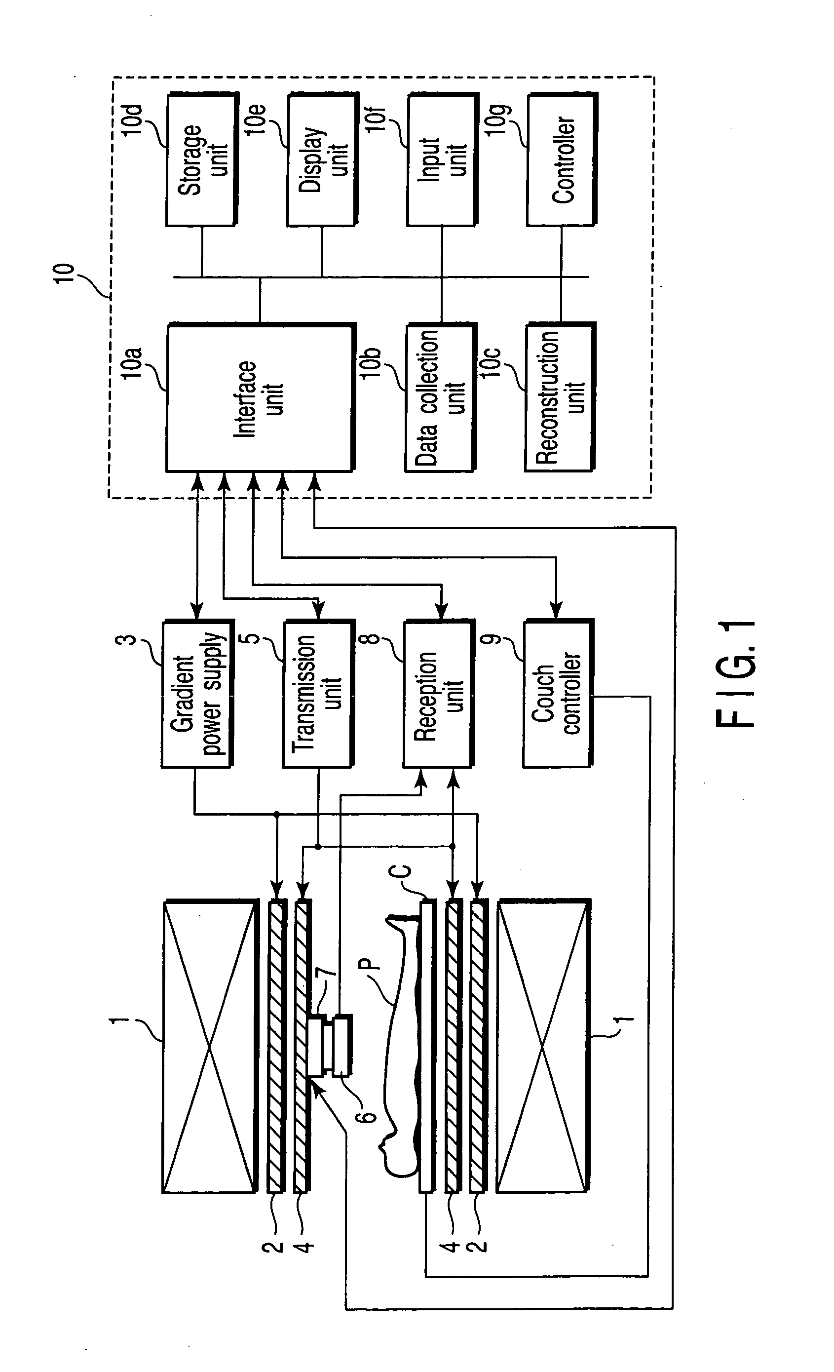
[0041]FIG. 1 is a diagram showing a configuration of an MRI apparatus according to a first embodiment of the invention. The MRI apparatus shown in FIG. 1 includes a static field magnet 1, a gradient magnetic field coil 2, a gradient power supply 3, a radio frequency coil 4, a transmission unit 5, a local probe 6, a position adjustment mechanism 7, a reception unit 8, a couch controller 9, and a computer system 10.

[0042] The static field magnet 1 has a hollow cylindrical shape and generates a uniform static magnetic field in an inside space. For example, a permanent magnet, a superconducting magnet, and the like are used as the static field magnet 1.

[0043] The gradient magnetic field coil 2 has a hollow cylindrical shape and is arranged inside the static field magnet 1. Three coils corresponding to axes X, Y, and Z orthogonal to one another are combined in the gradient magnetic field coil 2. In the gradient magnetic field coil 2, the gradient power supply 3 separately supplies curr...

second embodiment

[0074]FIG. 6 is a block diagram showing a configuration of an MRI apparatus according to a second embodiment of the invention. FIG. 7 and FIGS. 8A, 8B and 8C are views showing a configuration of a moving mechanism of a reception coil in FIG. 6. For the sake of convenience of the description, the axial directions X, Y, and Z are defined as shown in the drawings.

[0075] As shown in FIG. 6, the MRI apparatus of the second embodiment includes a gantry 21, a couch 22, a static field magnet 23, a gradient magnetic field coil 24, a radio frequency coil 25, reception coils 26a, 26b, 26c and 26d, a first moving mechanism 27, a second moving mechanism 28, a distance measuring sensor 29, a sensor controller 30, a gradient magnetic field drive unit 31, a transmission unit 32, a moving mechanism controller 33, a reception unit 34, a data collection unit 35, a computer 36, a console 37, a display 38, and a sequence controller 39.

[0076] In FIG. 6, the gantry 21 shows a cross section taken on a Y-...

third embodiment

[0106]FIG. 10 is a diagram showing a configuration of an MRI apparatus according to a third embodiment of the invention. For the sake of convenience of the description, the axial directions X, Y, and Z are defined as shown in FIG. 10.

[0107] As shown in FIG. 10, the MRI apparatus of the third embodiment includes a gantry 51, a couch 52, reception coils 53 and 54, a wire 55, pulleys 56 and 57, a hoisting device 58, a sensor 59, and a controller 60.

[0108] In FIG. 10, the gantry 51 shows the cross section taken on the Y-Z plane. The static field magnet, the gradient magnetic field coil, the radio frequency coil, and the like are provided in the gantry 51. However, these components are omitted in FIG. 10. In addition, the MRI apparatus according to the third embodiment includes well-known various elements for performing the imaging. However, only the characteristic elements are shown in FIG. 10, and the other elements are omitted in FIG. 10.

[0109] The couch 52 includes a double type o...


PUM


Abstract

A magnetic resonance imaging apparatus of the invention comprises a static magnetic field generation unit which generates a static magnetic field in a gantry, a gradient magnetic field generation unit which applies a gradient magnetic field to a object in the static magnetic field, a radio frequency coil which receives a magnetic resonance signal from the object to which the gradient magnetic field is applied, a contour detection unit which detects a contour of the object, a coil movement unit which moves the radio frequency coil on the basis of the detected contour while the radio frequency coil is placed near and far relative to the object, and an image generation unit which generates a magnetic resonance image on the basis of the received magnetic resonance signal.

Description

CROSS-REFERENCE TO RELATED APPLICATIONS [0001] This application is based upon and claims the benefit of priority from prior Japanese Patent Applications No. 2003-405779, filed Dec. 4, 2003; and No. 2004-042863, filed Feb. 19, 2004, the entire contents of both of which are incorporated herein by reference. BACKGROUND OF THE INVENTION [0002] 1. Field of the Invention [0003] The present invention relates to a magnetic resonance imaging (MRI) apparatus which utilizes a magnetic resonance phenomenon to generate a magnetic resonance image and an image generation method in the MRI apparatus. [0004] 2. Description of the Related Art [0005] A magnetic resonance imaging apparatus is one which visualizes chemical and physical micro information of a substance or observes a chemical shift spectrum by utilizing the phenomenon in which a group of nucleus resonantly absorbs energy of a radio frequency magnetic field rotated at a specific frequency when the group of nucleus having intrinsic magnetic...

Claims


Application Information

Patent Timeline
IPC IPC(8): G01R33/341
CPCG01R33/341
Inventor YASUHARA, YASUTAKEOKAMOTO, KAZUYAYAMANAKA, MASAAKIISHII, MANABUIGARASHI, TSUTOMUKUHARA, SHIGEHIDE
Owner TOSHIBA MEDICAL SYST CORP
Why Eureka
Try Eureka