Tree-based compositing system

a compositing system and tree technology, applied in the direction of electric controllers, instruments, ignition automatic control, etc., can solve the problems of high ram requirements, high cost, difficult to run at high speed,

Inactive Publication Date: 2005-06-09
CANON KK
View PDF8 Cites 28 Cited by
  • Summary
  • Abstract
  • Description
  • Claims
  • Application Information

AI Technical Summary

Benefits of technology

[0071] Arrangements according to the invention can render an expression tree consisting of different shaped graphic objects, and having differing overlap, without the need for complicated clippings on the intersecting areas, and without redundant instructions being sent to the fill generation stage or the comp

Problems solved by technology

There are essentially two problems with this technique.
For high-resolution color printers the amount of RAM required is very large, typically in excess of 100 Mbytes, which is costly and difficult to run at high speed.
The second problem is that many pixels, which are painted (rendered), are over-painted (re-rendered) by later objects.
Painting these pixels with the earlier objects is a waste of time.
There are some penalties with this technique, however.
Also, the technique of banding does not solve the problem of the cost of over-painting.
This technique overcomes the large frame store problem, however it still suffers from the over-painting problem.
Further, that document notes that one difficulty encountered with implementation is that, in many cases, rendering apparatus do not deal adequately with compositing of objects comprising pixels having associated opacity values.
However it complicates the expression tree when the left and right leave

Method used


Image

  • Tree-based compositing system
  • Tree-based compositing system
  • Tree-based compositing system

Examples


Embodiment Construction

[0148] Where reference is made in any one or more of the accompanying drawings to steps and / or features, which have the same reference numerals, those steps and / or features have for the purposes of this description the same function(s) or operation(s), unless the contrary intention appears.

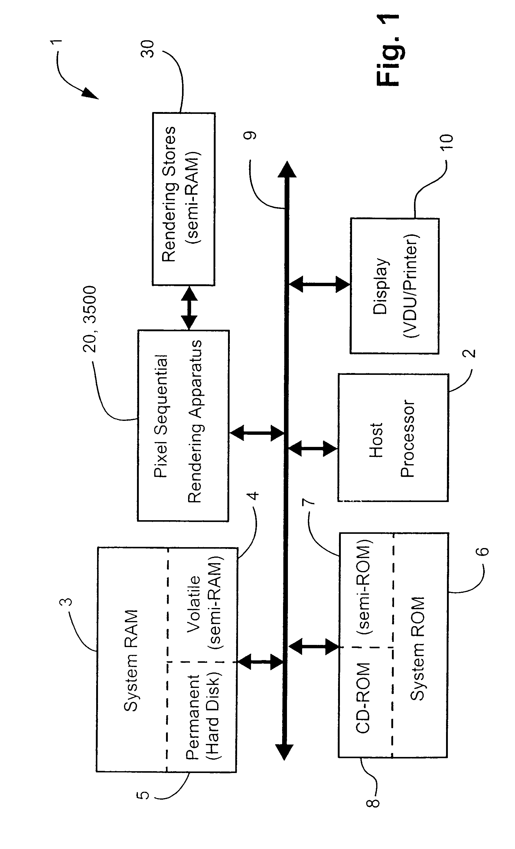
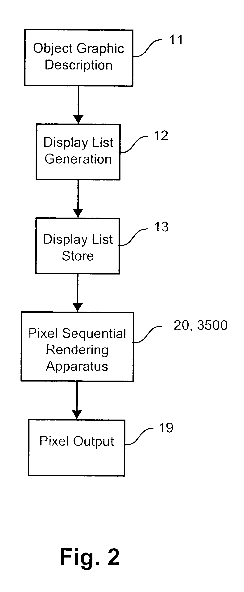
[0149] For a better understanding of a pixel sequential rendering system 1, a brief overview of the system 1 is first undertaken in Section 1.0. Then follows a brief discussion in Section 2.0 of the driver software for interfacing between a third party software application and the pixel sequential rendering apparatus 20, 3500 of the system 1. An overview of a prior art pixel sequential rendering apparatus 20 is then discussed in Section 3.0. The salient features of the present disclosure including a pixel sequential rendering apparatus 3500 are described in Section 4.0 and build upon the arrangements described in Sections 1.0, 2.0 and 3.0. As will become apparent, the pixel sequential rendering a...


PUM


Abstract

A method of rendering a graphical image described by an expression tree is disclosed. The expression tree has one or more parent nodes and one or more leaf nodes, each parent node representing a graphical operator and having branches to respective descendent nodes. Each of the leaf node represents a graphic object. The method determines regions of one or more pixel locations in an output space of the image, with each region corresponding to a combination in the image of one or more the graphical objects. Next, for each said region, an activity state of corresponding parent nodes is determined using a predefined function for each corresponding operator. The method then generates, in parallel (1098), for each active one of the operators, compositing instructions and pixel generation instructions. The compositing instructions are stored in an operator queue and pixel colors are generated using the pixel generation instructions, the pixel colors being buffered in an operand queue (1300). Lastly, the generated pixel colors are composited (1400), for each pixel in the region, using the operators defined in the operator queue, to output (800) a composited pixel value for each pixel in the region. Other processing operations including operator reduction, flat color bypass, and operand comparison are also discussed.

Description

CROSS-REFERENCE TO RELATED PATENT APPLICATION [0001] This application claims the right of priority under 35 U.S.C. § 119 based on Australian Patent Application No. 2003906614, filed 28 Nov. 2003, which is incorporated by reference herein in its entirety as if fully set forth herein. FIELD OF THE INVENTION [0002] The present invention relates generally to rendering graphic object based images. In particular, the present invention relates to a method and apparatus for generating instructions for a directed acyclic graph, commonly known as an expression tree. The invention also relates to a method and apparatus for rendering an expression tree into a raster pixel image. The invention also relates to a computer readable medium comprising a computer program for implementing any of the aforesaid methods. BACKGROUND [0003] When a computer application provides data to a device for printing and / or display, an intermediate description of the page is often given to the device driver software i...

Claims


Application Information

Patent Timeline
IPC IPC(8): G06T11/40G09G5/36
CPCG06T11/40
Inventor CHEN, YU-LING
Owner CANON KK
Why Eureka
Try Eureka