Liquid crystal display and method of manufacturing the same

a technology of liquid crystal display and liquid crystal display, which is applied in the direction of identification means, instruments, optics, etc., can solve the problems of increased manufacturing cost of liquid crystal display, large differences in color of light reflected by reflective areas, etc., and achieve high display characteristics

Active Publication Date: 2005-06-09
AU OPTRONICS CORP
View PDF16 Cites 80 Cited by
  • Summary
  • Abstract
  • Description
  • Claims
  • Application Information

AI Technical Summary

Benefits of technology

[0025] It is an object of the invention to provide a transflective liquid crystal display which can achieve high display characteristics in both of reflective and transmissive modes and a method of manufacturing the same.
[0027] The invention makes it possible to provide a transflective liquid crystal display which can achieve high display characteristics in both of the reflective and transmissive modes.

Problems solved by technology

A step for forming and patterning the insulators 130 is required for this transflective liquid crystal display to make the cell thickness of the reflective areas R smaller than the cell thickness of the transmissive areas T. This results in a problem in that the manufacturing cost of the liquid crystal display is increased because of increased complicatedness of manufacturing steps.
A problem therefore arises in that yellow is displayed in the reflective area while white is displayed in the transmissive area when the same voltage is applied to the transmissive area and the reflective area.
Another problem arises in that when intense external light enters during display in the transmissive mode, the color of light reflected by a reflective area can be greatly different from the color of light transmitted by a transmissive area.

Method used


Image

  • Liquid crystal display and method of manufacturing the same
  • Liquid crystal display and method of manufacturing the same
  • Liquid crystal display and method of manufacturing the same

Examples


embodiment 1-1

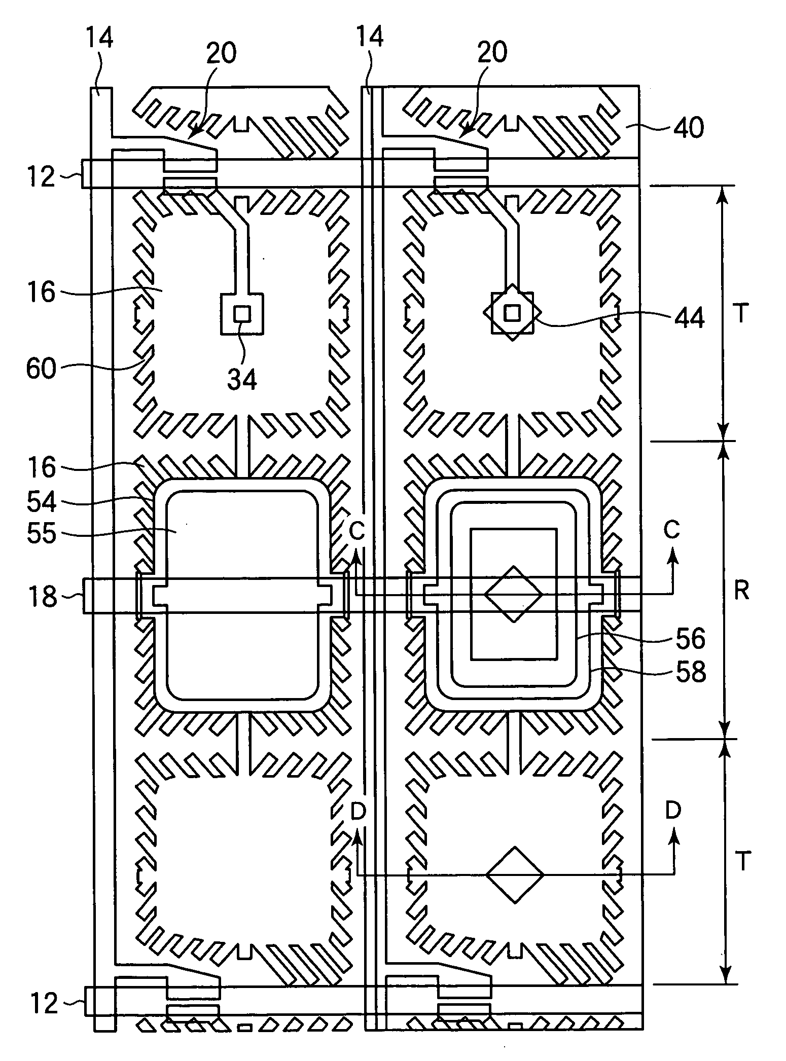
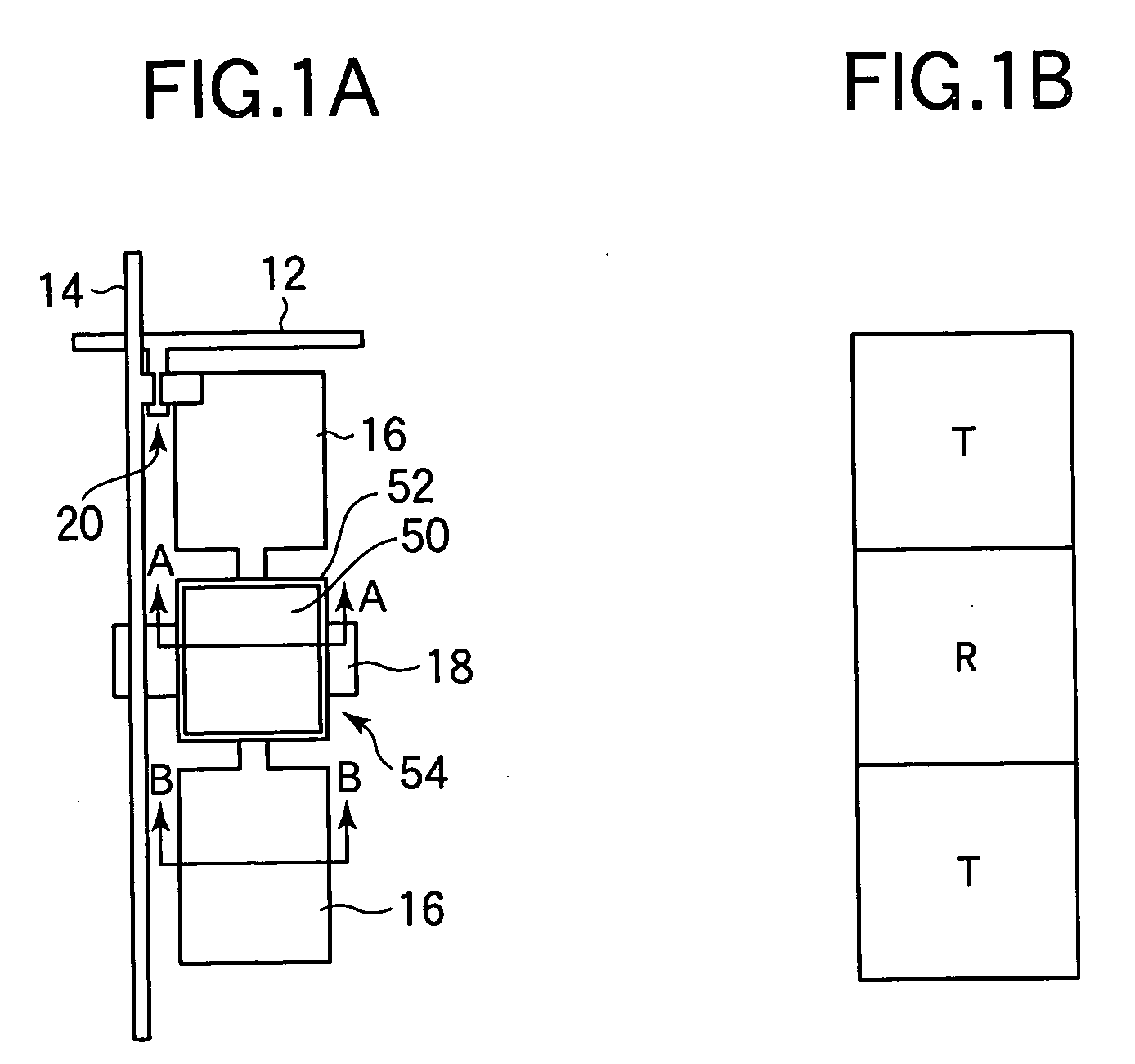
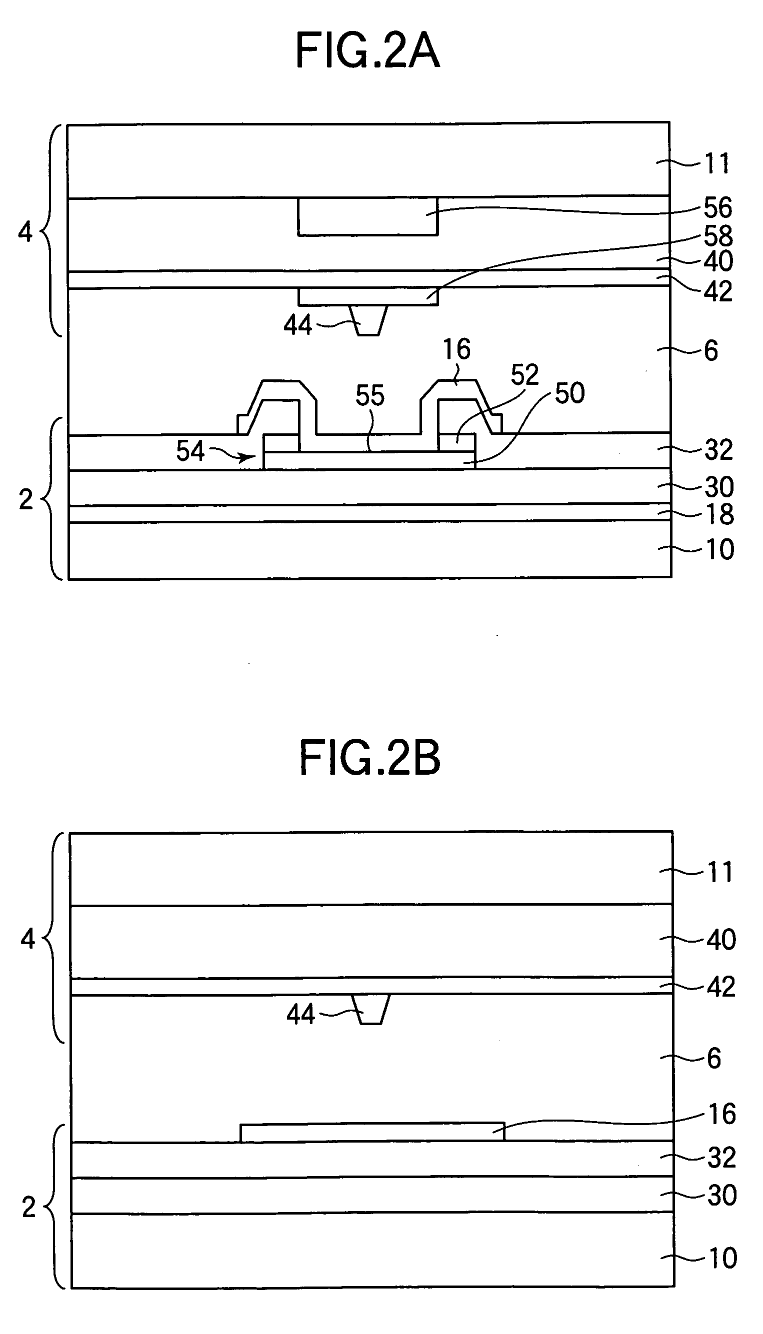
[0088] A liquid crystal display according to Embodiment 1-1 in the present mode for carrying out the invention will now be described. FIG. 3 shows a configuration of a pixel of the liquid crystal display of the present embodiment. A configuration of a TFT substrate 2 is shown on the left side of FIG. 3, and FIG. 3 shows the TFT substrate 2 and an opposite substrate 4 in an overlapping relationship with each other on the right side thereof. FIG. 4A shows a sectional configuration taken along the line C-C in FIG. 3, and FIG. 4B shows a sectional configuration taken along the line D-D in FIG. 3. As shown in FIGS. 3, 4A and 4B, one pixel region is divided into a reflective area R which is provided in the middle thereof and two transmissive areas T which are provided above and under the reflective area R respectively in FIG. 3.

[0089] In a transmissive area T, a pixel electrode 16 is formed in a substantially rectangular shape (e.g., a square shape). At the periphery of the pixel electro...

embodiment 1-2

[0093] A liquid crystal display according to Embodiment 1-2 in the present mode for carrying out the invention will now be described. FIG. 6 shows a sectional configuration of a pixel of the liquid crystal display of the present embodiment. While a CF layer 40 is formed on a transparent resin layer 56 in the above described Embodiment 1-1, a transparent resin layer 56 and a CF layer 40 are formed in reverse order in the present embodiment as shown in FIG. 6. Specifically, after removing a part of a CF layer 40 (e.g., a central part of a reflective area R) entirely in the thickness direction of the layer, a transparent resin layer 56 is formed on the same. Thus, a transparent area having no CF layer 40 is formed in a part of a reflective area R to improve the reflectivity of the same. Further, a common electrode 42, a transparent resin layer 58 for decreasing an effective voltage applied to a liquid crystal 6 and an alignment controlling protrusion 44 are sequentially formed on the t...

embodiment 1-3

[0095] A liquid crystal display according to Embodiment 1-3 in the present mode for carrying out the invention will now be described. FIG. 8 shows a configuration of a pixel of the liquid crystal display of the present embodiment. FIG. 9A shows a sectional configuration of the liquid crystal display taken along the line E-E in FIG. 8, and FIG. 9B shows a sectional configuration of the liquid crystal display taken along the line F-F in FIG. 8. In the present embodiment, the configuration shown in FIG. 7 is elaborated, and a measure is taken to improve a region where a CF layer 40 is removed. First, a CF layer 40, from which an entire area where a reflector 54 is to be formed (a reflective area R) have been removed, is formed on a TFT substrate 2. A common electrode 42 is thereafter formed on the CF layer 40. Then, a transparent resin layer 57 is formed so as to fill the area where the CF layer 40 has been removed, and an alignment controlling protrusion 44 is formed on the transparen...


PUM

PropertyMeasurementUnit
thicknessaaaaaaaaaa
thicknessaaaaaaaaaa
heightaaaaaaaaaa

Abstract

The invention relates to a transflective liquid crystal display capable of display in both of transmissive and reflective modes and a method of manufacturing the same and provides a transflective liquid crystal display which can achieve high display characteristics in both of the transmissive and reflective modes. A configuration is employed which includes a liquid crystal display panel having a pair of substrates and a liquid crystal layer sealed between the substrates, a pixel region including a reflective area having a reflector for reflecting light entering from the side of one of the pair of substrates and a transmissive area for transmitting light entering from the side of the other of the pair of substrates toward the one of the pair of substrates, a backlight unit having a reflector and a light guide plate for reflecting the light which has entered the transmissive area from the side of the one of the pair of substrates and which has been transmitted by the area to cause the light to enter the transmissive area again from the side of the other of the pair of substrates, and a color filter layer formed only in the transmissive area of the pixel region.

Description

BACKGROUND OF THE INVENTION [0001] 1. Field of the Invention [0002] The present invention relates to a liquid crystal display and a method of manufacturing the same and, more particularly, to a transflective liquid crystal display capable of display in both of transmissive and reflective modes and a method of manufacturing the same. [0003] 2. Description of the Related Art [0004] Recently, active matrix liquid crystal displays having a thin film transistor (TFT) at each of pixels are widely used as displays in every field of application. Under such a circumstance, transflective liquid crystal displays capable of display in both of reflective and transmissive modes have been put in use as displays for mobile terminals or notebook type personal computers. [0005]FIGS. 47A and 47B show a configuration of a transflective liquid crystal display according to the related art disclosed in Non-Patent Document 1. FIG. 47A shows a configuration of a pixel of the transflective liquid crystal dis...

Claims


Application Information

Patent Timeline
Patent Type & Authority Applications(United States)
IPC IPC(8): G02F1/133G02F1/1337G02F1/1333G02F1/1335G02F1/1343G02F1/136G09F9/30G09F9/35H01L21/00H01L21/336H01L29/786
CPCG02F1/133514G02F1/133707G02F1/133555G02F1/1335
Inventor YOSHIDA, HIDEFUMITASAKA, YASUTOSHITASHIRO, KUNIHIROOHMURO, KATSUFUMIKAMADA, TSUYOSHIUEDA, KAZUYASHIBASAKI, MASAKAZU
Owner AU OPTRONICS CORP
Why Eureka
Try Eureka