Universal ophthalmic examination device and ophthalmic examination method

a technology of ophthalmology and examination device, which is applied in the field of universal ophthalmology examination device and ophthalmological examination method, can solve the problems of limited technique, increased structural size and weight, and low geometric resolution of images, so as to reduce light burden, shorten flash time, and increase dynamic range

Active Publication Date: 2005-06-09
IMEDOS INTELLIGENTE OPTISCHE SYST DER MEDIZIN & MESSTECHNIK GMBH
View PDF3 Cites 54 Cited by
  • Summary
  • Abstract
  • Description
  • Claims
  • Application Information

AI Technical Summary

Benefits of technology

[0020] By influencing the illumination by means of an individual element arranged in the illumination beam path, multifunctionality can be achieved in that the characteristics of the light in the illumination beam path are changed so as to be adapted to function, so that there is no need for a separate stimulating illuminator that is blended in through an additional beam path.
[0036] Another surprising effect results through the use of an optical light modulator which switches only the visible spectral range and is transparent for the infrared spectral range. When the switching of the light modulator is synchronized with an infrared camera, provided as an alternative, and a camera for the visible spectrum with blocked infrared, both mydriatic retinal cameras and non-mydriatic cameras can be used. This results in the further advantage that vascular analysis and functional imaging can be carried out as non-mydriatic examinations. Simple Insertion, Retrofit

Problems solved by technology

While image documentation in flash mode generates high-quality images, the succession in time on individual images per second is limited in terms of technique and also with respect to the light stress for patients.
In addition, devices with flash beam paths are cost-intensive and lead to an increase in structural size and weight.
Continuous illumination, on the other hand, enables continuous sequences of image recordings, e.g., in video mode, but the images have only a low geometric resolution and poor image quality because of the light stress limit and the continuous illumination itself.
While stepping up the control of the lamps that are used improves the image quality with reasonable light burden, the flickering of the light that is caused by the inertia of the lamp and is perceptible to the patient leads to corresponding anticipatory attitudes, blinking, squinting and eye movements which again leads to considerable impairment of image quality.
Although this offers the advantage that the light from any light sources can be superimposed or alternately switched, it is disadvantageous that stimulation necessitates another device whose light must be brought to the retina on an additional beam path by means of a splitter mirror.
Since the modified flash beam path serves as a separate beam path, there is the disadvantage that high-quality image documentation by means of flash light for functional imaging is discarded.

Method used


Image

  • Universal ophthalmic examination device and ophthalmic examination method
  • Universal ophthalmic examination device and ophthalmic examination method

Examples


Embodiment Construction

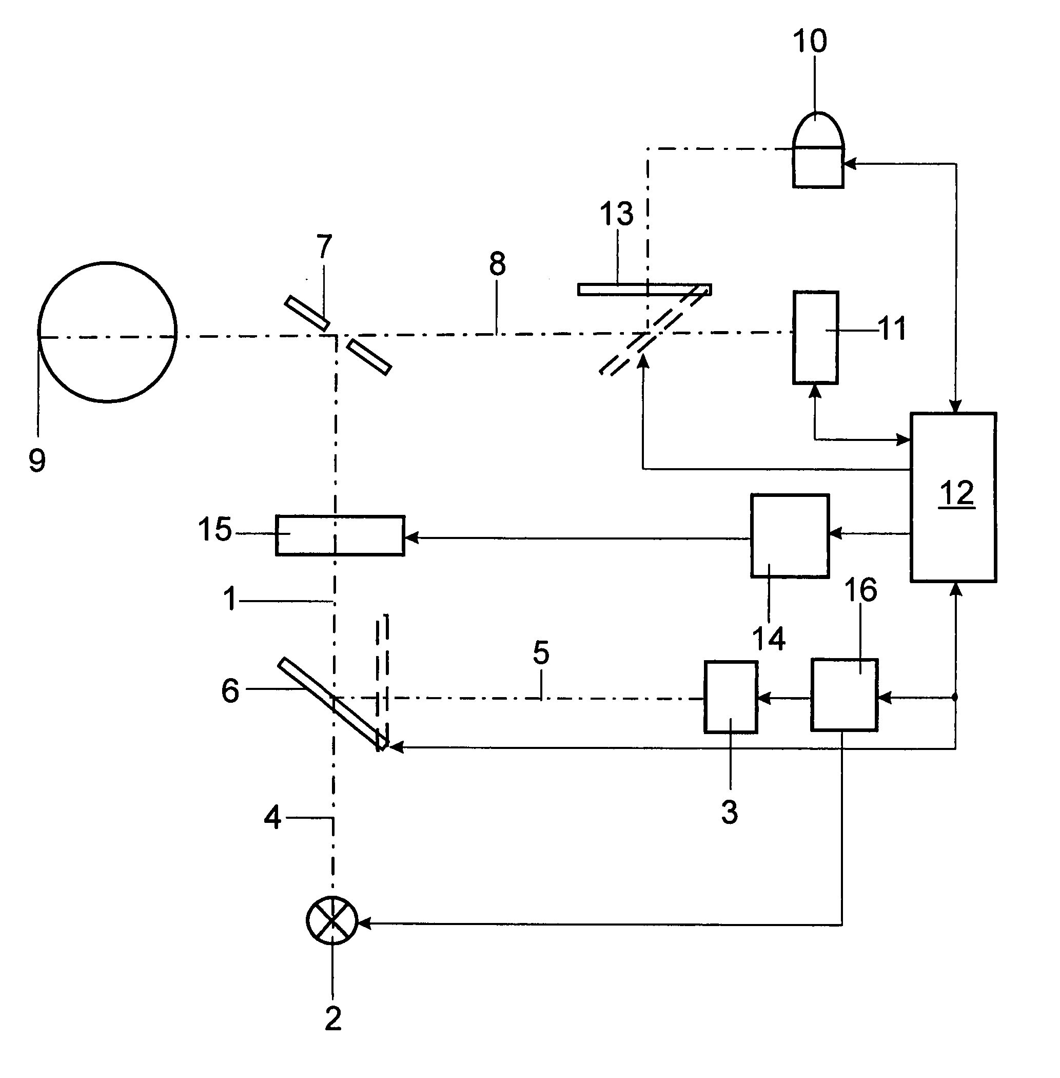
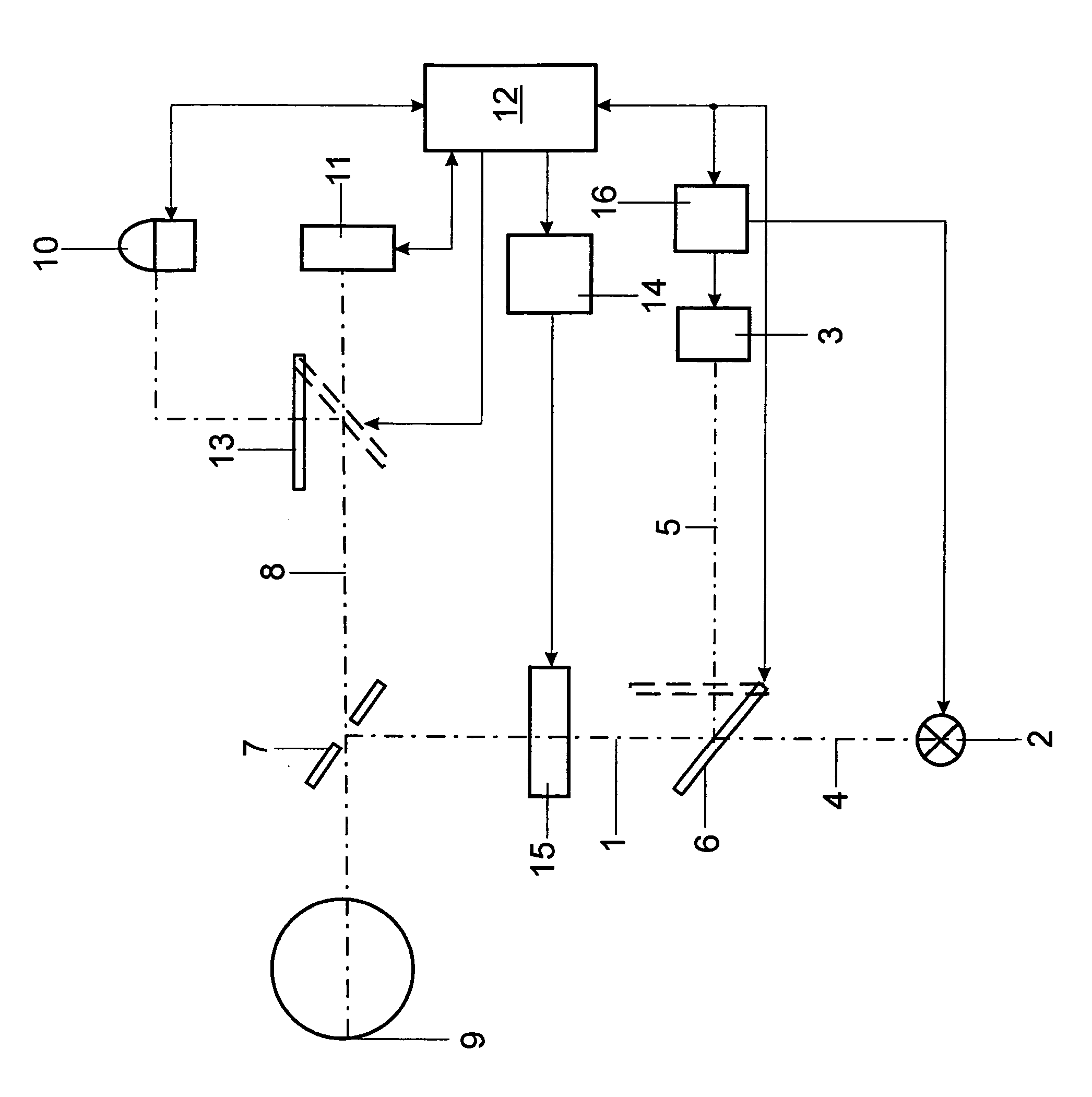
[0040] The examination device has an illumination beam path 1 serving as a common beam path for an illumination device 2 which radiates continuously in the visible and infrared range and which is constructed as a halogen lamp and a flash illumination device 3. The light of the two illumination devices 2 and 3 can be coupled into the illumination beam path 1 alternatively along separate beam paths 4 and 5 by means of a tilting mirror 6.

[0041] A pinhole mirror 7 is inserted in the illumination beam path 1. An imaging beam path 8 passes through the central opening of the pinhole mirror 7 and the illumination light is directed to the ocular fundus 9 over the area surrounding the central opening by means of optically imaging elements, not shown. Light reflected by the ocular fundus 9 travels along the imaging beam path 8 and via optically imaging elements, again not shown, for the image recording. For this purpose, in the present embodiment example, two image recording devices 10 and 11...


PUM


Abstract

A universal ophthalmic examination device and an ophthalmic examination method have the object of combining in an inexpensive apparatus in a simple manner the device-related requirements for image generation, measurement and functional imaging for carrying out visual stimulation and highly time-resolved and highly spatially resolved image documentation using continuous illumination and flash mode and the requirements for measurements in the infrared spectral region and visible spectral region with a time regime that can be freely selected to a great extent. The light of at least one light source is modified in a program-oriented manner with respect to its intensity curve and / or time curve with a temporally defined relationship to the adjustments of the at least one light source, of the image recording and of the evaluation for purposes of adaptive matching to an examination task in the illumination beam path by an individual, shared light manipulator and is used as modified light for illumination and for selective stimulation.

Description

CROSS-REFERENCE TO RELATED APPLICATION [0001] This application claims priority of German Application No. 103 57 734.3, filed Dec. 5, 2004, the complete disclosure of which is hereby incorporated by reference. BACKGROUND OF THE INVENTION [0002] a) Field of the Invention [0003] The invention is directed to a universal ophthalmic examination device which has, in combination with a central control unit, at least one primary light source in an illumination beam path directed to an object being examined and at least one image recording and evaluating unit for documenting and / or for measuring at least partial areas of the object being examined, and electronically switchable elements for beam path switching. [0004] The invention is further directed to an ophthalmic examination method in which an object to be examined is illuminated and selectively stimulated by an illumination beam path for recording images with light of at least one light source and in which examination results are derived...

Claims


Application Information

Patent Timeline
Patent Type & Authority Applications(United States)
IPC IPC(8): A61B3/00A61B3/12A61B3/14
CPCA61B3/14A61B3/1241
Inventor VILSER, WALTHARDSEIFERT, BERND-ULLRICHKASSNER, CHRISTINE
Owner IMEDOS INTELLIGENTE OPTISCHE SYST DER MEDIZIN & MESSTECHNIK GMBH
Why Eureka
Try Eureka