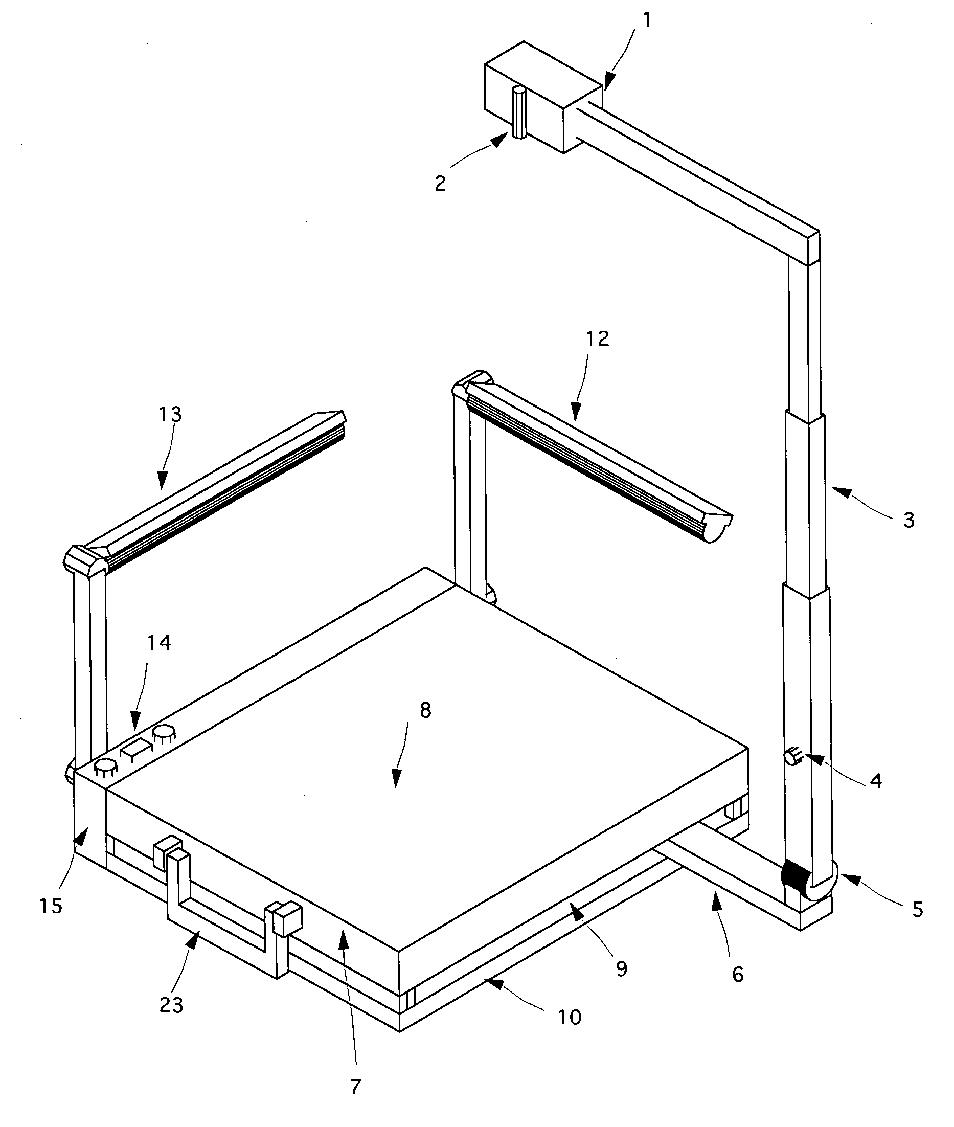
Portable digital visual presenter specially designed to be used with 14 x 17 inches films on which the MRI and CAT scans are commonly printed
- Summary
- Abstract
- Description
- Claims
- Application Information
AI Technical Summary
Benefits of technology
Problems solved by technology
Method used
Image
Examples
first embodiment
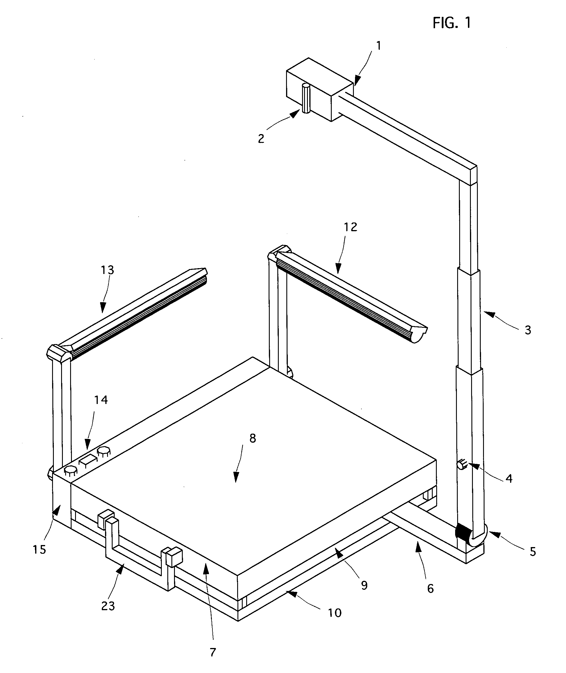
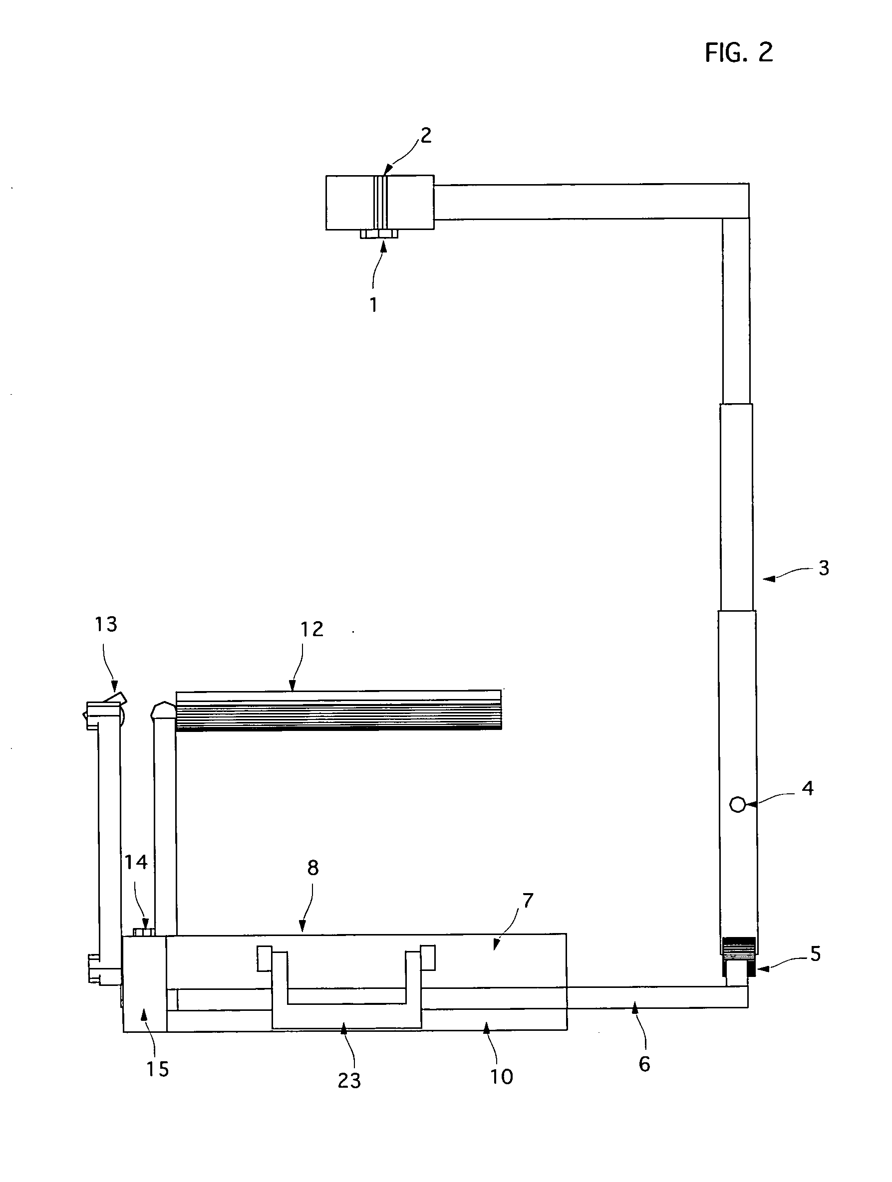
[0025]FIG. 3. is a transparent left side view of the Portable Digital Visual Presenter according to the present invention, wherein the metal bar 18 and the input / output ports 16 are clearly shown.
[0026] The housing's groove 9, wherein the metal bar 18 moves, and the sliding mechanism 11 are best shown in FIGS. 4 and 5. The sliding mechanism 11 works as follow: The telescopic arm part 3 is coupled by a hinge 5 to a lateral arm 6 that goes into the groove 9 parallel to the stage 8. A low friction sliding mounting 17 mounts the lateral arm 6 into the metal bar 18, which is also positioned in two low friction plastic square sliding bars 19. The sliding mechanism 11 slides over the low friction bottom 10 allowing the metal bar 18 to move in the horizontal axis of the housing 7 and the lateral arm 6 to move alongside the metal bar 18 in the vertical axis of the housing 7 so that the centre of the digital camera's shooting area reaches every sector of the stage 8. An important feature of t...
second embodiment
[0030]FIG. 8 is a perspective view of the Portable Digital Visual Presenter in a using state, according to the present invention. The Portable Digital Visual Presenter comprises a digital camera 1, a telescopic arm part 24 and a housing 27, which are attached to one another so that each part can be folded to make the Digital Visual Presenter portable. The size thereof when collapsed is shown in FIG. 12. The camera controls 14 are built-in in the control box 31, located in the front side of the housing 27, allowing the user to adjust the image settings such as zoom, focus, contrast, brightness and colour. The telescopic arm part 24 to which the digital camera 1 is attached is fixed to the housing 27 so that the centre of the camera's shooting area is always the same. Attached to the digital camera 1 is a laser pointer 2 so that it can be seen exactly where the said centre is positioned.
[0031] Referring now to FIG. 9 of the drawings, the numeral 31 indicates the control box located pr...
PUM
 Abstract
Description
Claims
Application Information
 - R&D
- Intellectual Property
- Life Sciences
- Materials
- Tech Scout
- Unparalleled Data Quality
- Higher Quality Content
- 60% Fewer Hallucinations
Browse by: Latest US Patents, China's latest patents, Technical Efficacy Thesaurus, Application Domain, Technology Topic, Popular Technical Reports.
© 2025 PatSnap. All rights reserved.Legal|Privacy policy|Modern Slavery Act Transparency Statement|Sitemap|About US| Contact US: help@patsnap.com


