
Communication network system

a communication network and network technology, applied in the field of communication network systems, can solve the problems of increasing the amount of route information flowing in the network and increasing the load on the network side, and achieve the effect of reducing processing load

Inactive Publication Date: 2005-06-09
FUJITSU LTD
View PDF25 Cites 15 Cited by
  • Summary
  • Abstract
  • Description
  • Claims
  • Application Information

AI Technical Summary

Benefits of technology

[0006] It is an object of the present invention to provide a technique that makes it possible to significantly reduce processing loads in a hierarchical network and a relay apparatus.
[0007] It is another object of the present invention to provide a technique that makes it possible to avoid automatic selection of a route, in which the number of ASs on the route is minimized, regardless of inconvenience in the case in which BGP-4 or the like is adopted as an inter-AS routing protocol, that is, regardless of the fact that a line is thin (a transmission bandwidth is narrow) or ASs are physically distant from one another.
[0008] It is still another object of the present invention to provide a technique that allows efficient communication as a hierarchical network as a whole.
[0009] It is still another object of the present invention to provide a technique that makes it possible to apply priority control according to parameters flexibly in a higher hierarchy network to be a base network.
[0010] It is still another object of the present invention to provide a technique where optimum routing processing is applicable according to various communication forms in a hierarchical network.
[0018] each of the third relay apparatuses in the edge positions in the upper hierarchy networks makes it possible to perform routing processing based on parameters for specifying a priority of a line in each section of the third relay apparatuses in an adjacent state.

Problems solved by technology

As a result, an amount of route information (routing information) flowing in the network increases, and a load on the network side increases.

Method used


Image

  • Communication network system
  • Communication network system
  • Communication network system

Examples


Embodiment Construction

[0069] Next, embodiments of the present invention will be explained with reference to the drawings.

[0070] [Schematic Structure and Functions of Communication Network System]

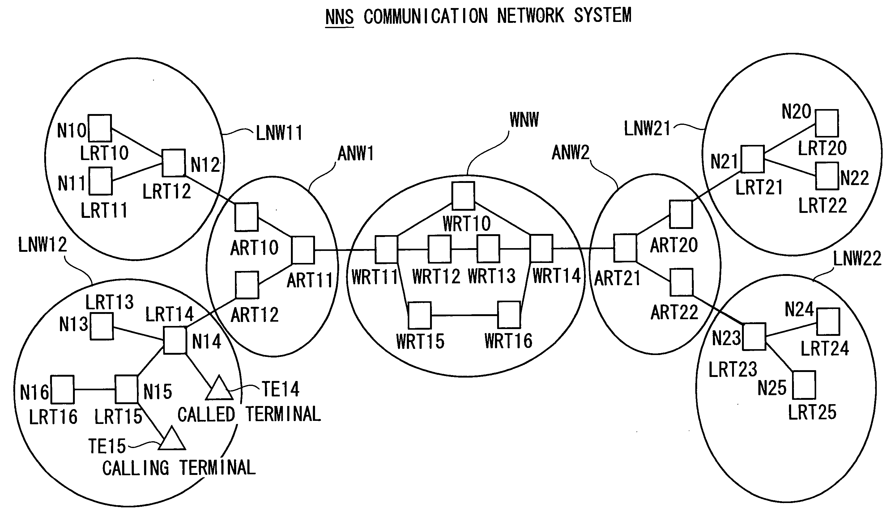
[0071] First, a schematic structure and functions of a communication network system according to an embodiment of the present invention will be explained with reference to FIG. 1.

[0072] A communication network system NNS applicable to the next generation is constituted by plural networks of three hierarchies, namely, a lower (first) hierarchy,,an intermediate (second) hierarchy, and an upper (third) hierarchy. Each of the plural networks of the three hierarchies functions as an autonomous system (AS).

[0073] This communication network system NNS includes local networks LNWs (LNW11, LNW12, LNW21, and LNW22)as networks of the lower hierarchy, includes area networks ANWs (ANW1 and ANW2) as networks of the intermediate hierarchy, and includes a wide network WNW as a network of the upper hierarchy.

[0074] The local ...


PUM


Abstract

A communication network system includes: a plurality of lower hierarchy networks, each having a plurality of first relay apparatuses; and an intermediate hierarchy network having a plurality of second relay apparatuses for connecting the plurality of lower hierarchy networks via the second relay apparatuses at the edge position line-connected to the first relay apparatuses at the edge position. Each of the first relay apparatuses has a first routing table that holds information limited to routing information corresponding to the first relay apparatus and routing information on at least one of the first relay apparatuses and the second relay apparatuses in the edge positions that come into an adjacent state. Each of the second relay apparatuses has a second routing table that holds information including routing information on at least one of the second relay apparatuses and the first relay apparatuses in the edge positions that come into an adjacent state.

Description

BACKGROUND OF THE INVENTION [0001] The present invention relates to a communication network system, in particular, a next-generation communication network system that adopts unique routing processing. [0002] In a conventional communication network system, since respective routers, which constitute an AS (Autonomous System) serving as a network having a certain operation policy, perform routing processing (route selection processing) in accordance with a routing protocol such as an RIP (Routing Information Protocol) or an OSPF (Open Shortest Path First), processing loads applied to the respective routers are large. As a result, an amount of route information (routing information) flowing in the network increases, and a load on the network side increases. [0003] Here, the RIP adopts a routing processing method of distance vectors, in which routers adjacent to each other exchange route information one after another to thereby make it possible to collect and set route information of the...

Claims


Application Information

Patent Timeline
IPC IPC(8): H04L12/56
CPCH04L45/04H04L45/02
Inventor NABAE, TAKEHIRO
Owner FUJITSU LTD
Learn More