Heating device, fixing device using the heating device and image forming apparatus using the fixing device

a technology of fixing device and heating device, which is applied in the direction of ohmic-resistance heating, electrographic process apparatus, instruments, etc., can solve the problems of long time, large environmental protection, and consumption of excess energy

Inactive Publication Date: 2005-06-09
RICOH KK
View PDF11 Cites 60 Cited by
  • Summary
  • Abstract
  • Description
  • Claims
  • Application Information

AI Technical Summary

Benefits of technology

[0022] a sub power source controller configured to control the sub power source such that a temperature of the auxiliary heater ...

Problems solved by technology

Recently, environmental protection becomes a major issue, and energy-saving image forming apparatus (such as copiers and printers) have been developed.
However, this technique has a drawback in that a considerable amount of electric power has to be supplied to the fixing device in a waiting state, resulting in consumption of excess energy.
However, if the energy consumption of a fixing device in a waiting state is zero, it takes a long time of from few minutes to tens minutes to raise the temperature of the heat roller of the fixing device to a predetermined fixing temperature (about 180° C.
), i.e., the fixing device has a long rise time.
Therefore, this fixing device is not practical.
Namely, a special electric construction is necessary for providing an electric power of 200 V. Therefore, this technique is not a general solution.
As mentioned above, it is difficult to shorten the rise time as long as a commercial power source of 100 V and 15 A is used.
This is because the maximum energy applied to the fixing device, which depends on the commercial electric power, is relatively low.
However, since a low voltage is constantly applied to the fixing device during a waiting state of the fixing device disclosed in JP-A 10-10913, the fixing device does not fully save energy.
The secondary batteries have a drawback in that the power decreases when charging and discharging are repeatedly performed.
In particular, the life of...

Method used


Image

  • Heating device, fixing device using the heating device and image forming apparatus using the fixing device
  • Heating device, fixing device using the heating device and image forming apparatus using the fixing device
  • Heating device, fixing device using the heating device and image forming apparatus using the fixing device

Examples


Embodiment Construction

[0044] The present invention will be explained referring to drawings.

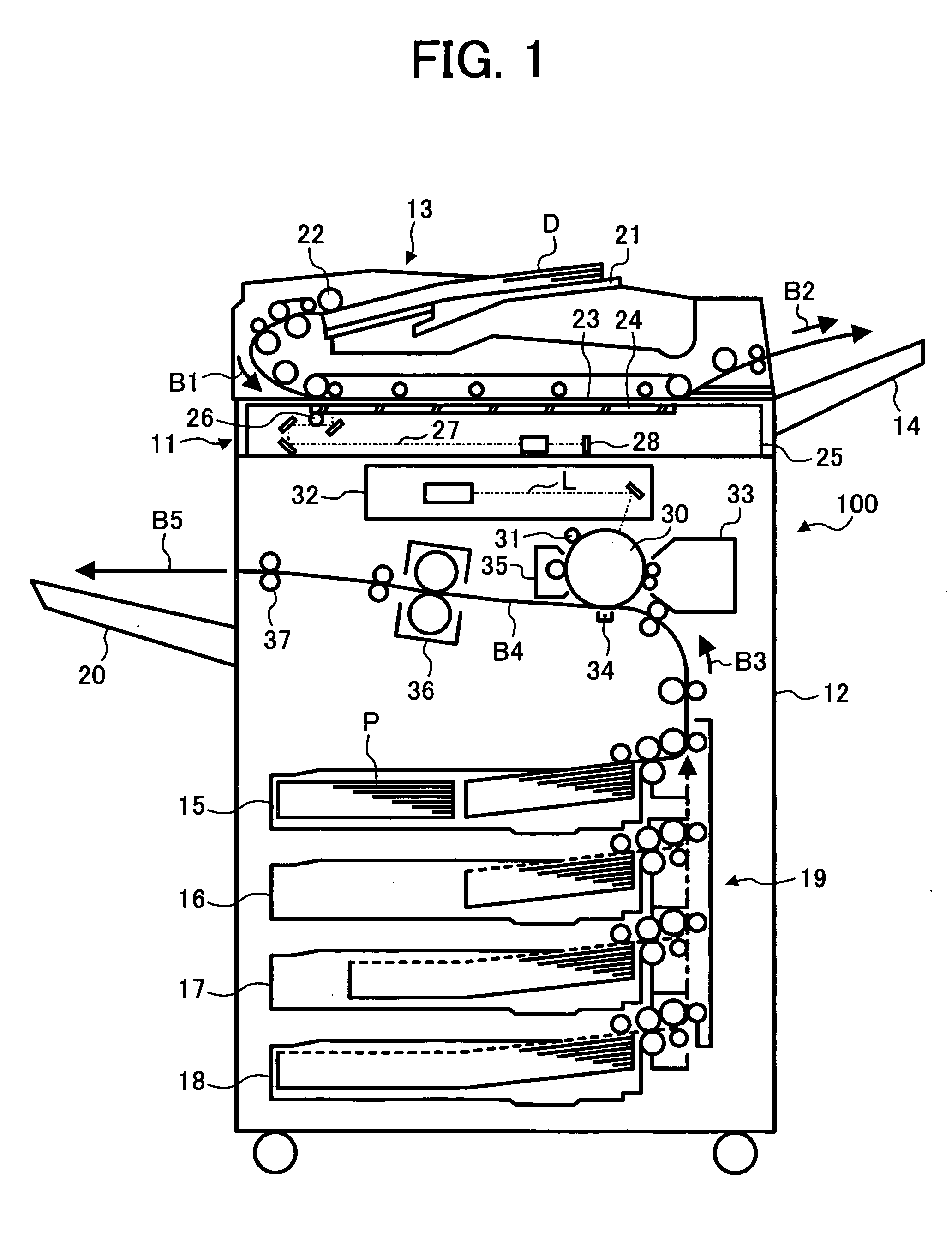
[0045]FIG. 1 is a schematic view illustrating the cross section of the image forming apparatus (e.g., copiers and printers) of the present invention. Referring to FIG. 1, numeral 100 denotes an image forming apparatus. The image forming apparatus 100 includes an image reading unit 11 configured to read an image of an original document; an image forming unit 12 configured to reproduce the original image; an automatic document feeder (ADF) 13; an original discharge tray 14; a paper feeding unit 19 including paper feeding cassettes 15-18; and a paper discharge tray 20 on which recording paper sheets bearing images thereon are stacked.

[0046] When a stack of original document sheets D is set on an original table 21 of the ADF 13 and a print key located at an operation panel (not shown) is pushed to order to copy the images of the original document sheets D, a pickup roller 22 is rotated to feed the uppermost sheet of ...


PUM


Abstract

A heating device including a main power source; a sub power source including a capacitor capable of charging and discharging; a heating member including a main heater and an auxiliary heater and configured to heat a material with the heater and the auxiliary heater, wherein the main heater and the auxiliary heater are supplied with electric power by the main power source and the sub power source; and a sub power source controller configured to control the sub power source such that a temperature of the auxiliary heater is controlled so as to be a target temperature, wherein the sub power source controller changes the target temperature, if necessary. A fixing device and an image forming apparatus including the heating device are also provided.

Description

BACKGROUND OF THE INVENTION [0001] 1. Field of the Invention [0002] The present invention relates to a heating device which heats various materials and devices, a fixing device which fixes a material (e.g., toner images) on a material (e.g., recording materials) using the heating device, and an image forming apparatus, such as copiers, printers and facsimiles, which forms a toner image on a recording material using the fixing device. [0003] 2. Discussion of the Background [0004] In image forming apparatus such as copiers, printers and facsimiles, an image is formed on a recording material such as plain papers and overhead projection sheets. In view of image qualities and running costs, electrophotography is typically used as the image forming method. Electrophotographic image forming methods include the steps of forming a toner image on a recording material; and fixing the toner image on the recording material upon application of heat and pressure thereto. [0005] As for the fixing m...

Claims


Application Information

Patent Timeline
IPC IPC(8): G03G15/00G03G15/20G03G21/00G03G21/14G03G21/20H05B3/00
CPCG03G15/5004G03G21/20G03G15/2039G03G2215/20G03G2215/00978
Inventor KISHI, KAZUHITOKATO, YASUHISAOKAMOTO, MASAMITSUKIOKA, YASUTADATAKAGI, HIROMASA
Owner RICOH KK
Why Eureka
Try Eureka