

Compact diagonal fan
a fan and diagonal technology, applied in the direction of machines/engines, stators, liquid fuel engines, etc., can solve the problems that small ventilators are rarely found with diagonal designs, and achieve the effects of reducing rotational speed, reducing noise, and improving air flow
- Summary
- Abstract
- Description
- Claims
- Application Information
AI Technical Summary
Benefits of technology
Problems solved by technology
Method used
Image

Examples
Embodiment Construction
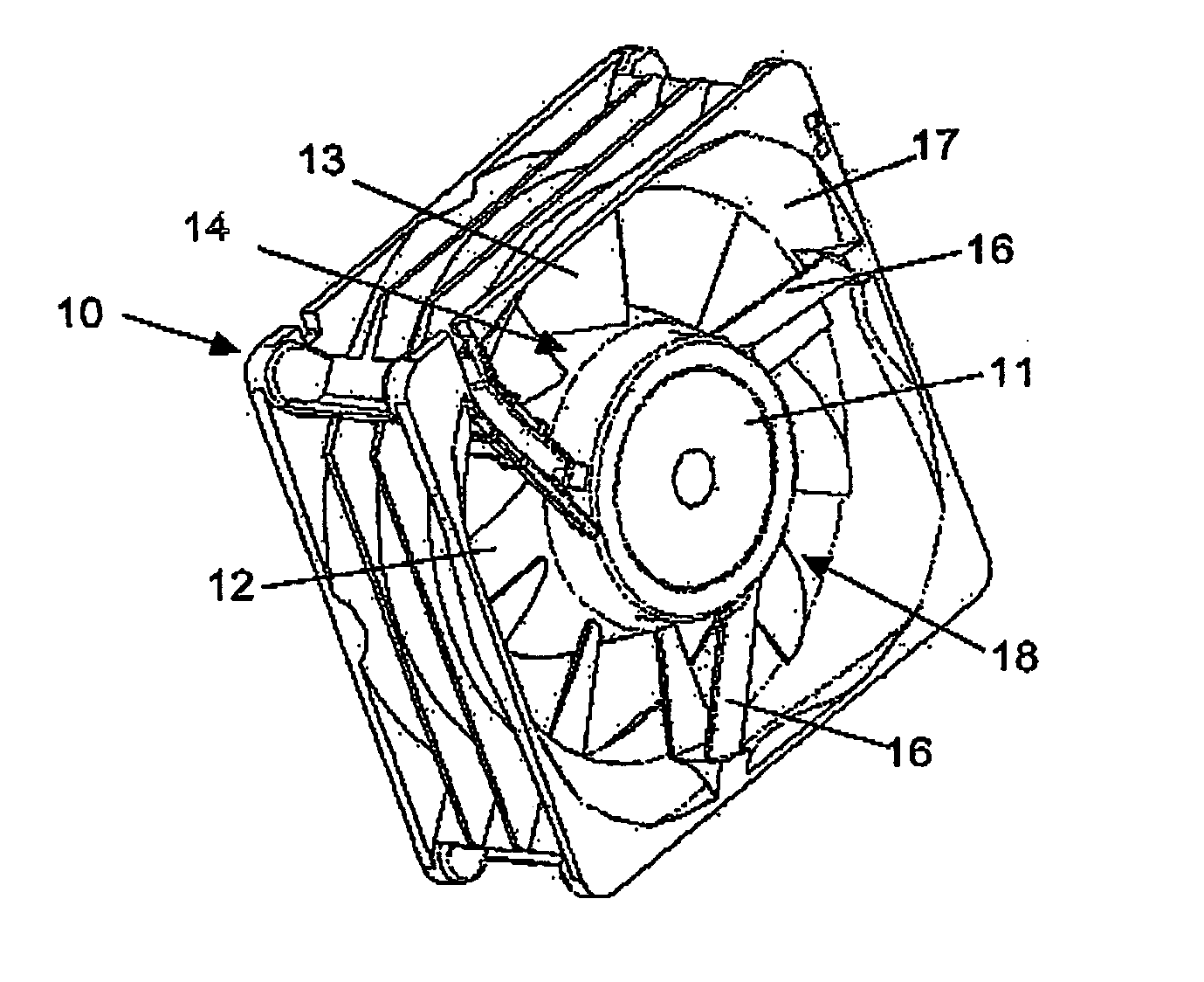
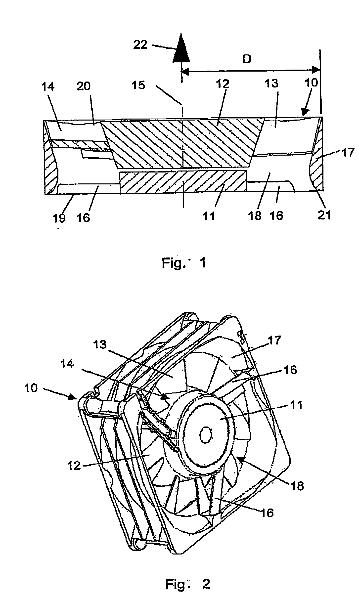
[0018] The fan illustrated in FIGS. 1 and 2 essentially comprises a housing 10, an electric motor 11 supported within the housing 10 whose hub 12, together with a plurality of blades 13 formed on the hub 12, go to make up the impeller 14 of the fan. The impeller 14 is rotatably supported about a rotational axis 15 and is driven by the electric motor 11. The electric motor 11 is held within the housing 10 by means of bridges 16 which essentially extend in a radially outwards direction.
[0019] The housing 10 comprises an air conduction sleeve 17 adapted to the diameter of the impeller 14. Together with the air conduction sleeve 17 surrounding the impeller, the hub encloses an essentially annular flow channel 18 which has an air intake opening 19 and an air exit opening 20. The air is sucked into the air intake opening 19, flows through the fan in the direction of flow 22 and is expelled again at the air exit opening 20.
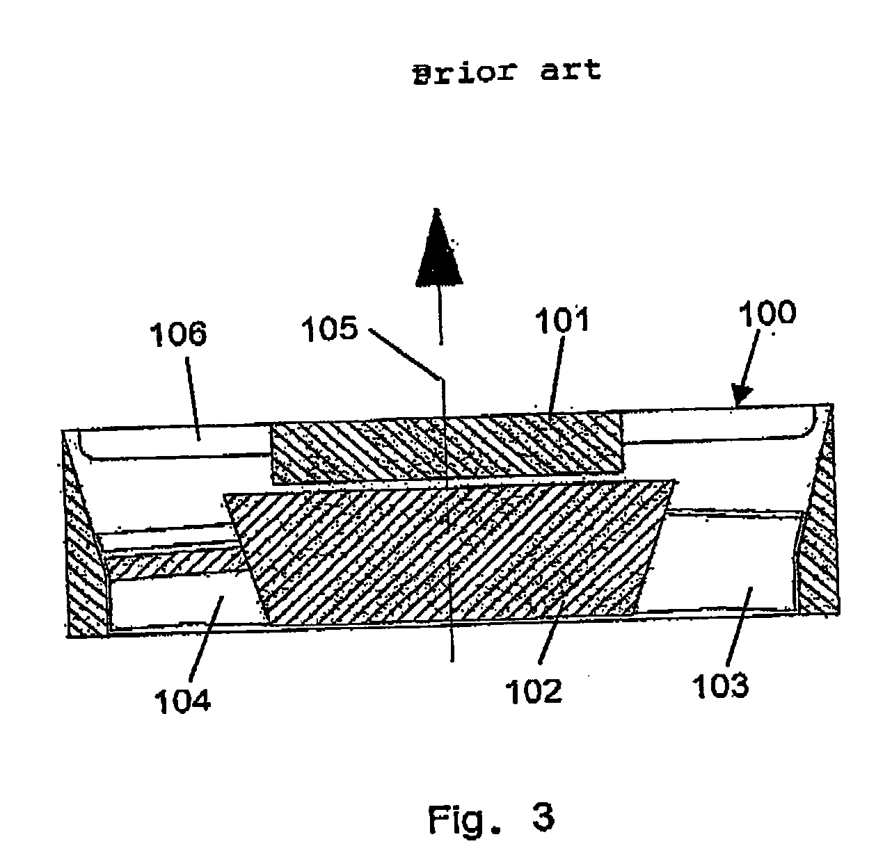
[0020] The hub 12 essentially takes the form of a truncated cone ...
PUM
 Abstract
Description
Claims
Application Information