Skeleton member structure

a skeleton and member technology, applied in the direction of shock absorption devices, elastic dampers, roofs, etc., can solve the problems of excessive internal pressure difficult reduction of the large weight of the structural member, so as to achieve the effect of easy formation

Inactive Publication Date: 2005-06-09
HONDA MOTOR CO LTD
View PDF7 Cites 18 Cited by
  • Summary
  • Abstract
  • Description
  • Claims
  • Application Information

AI Technical Summary

Benefits of technology

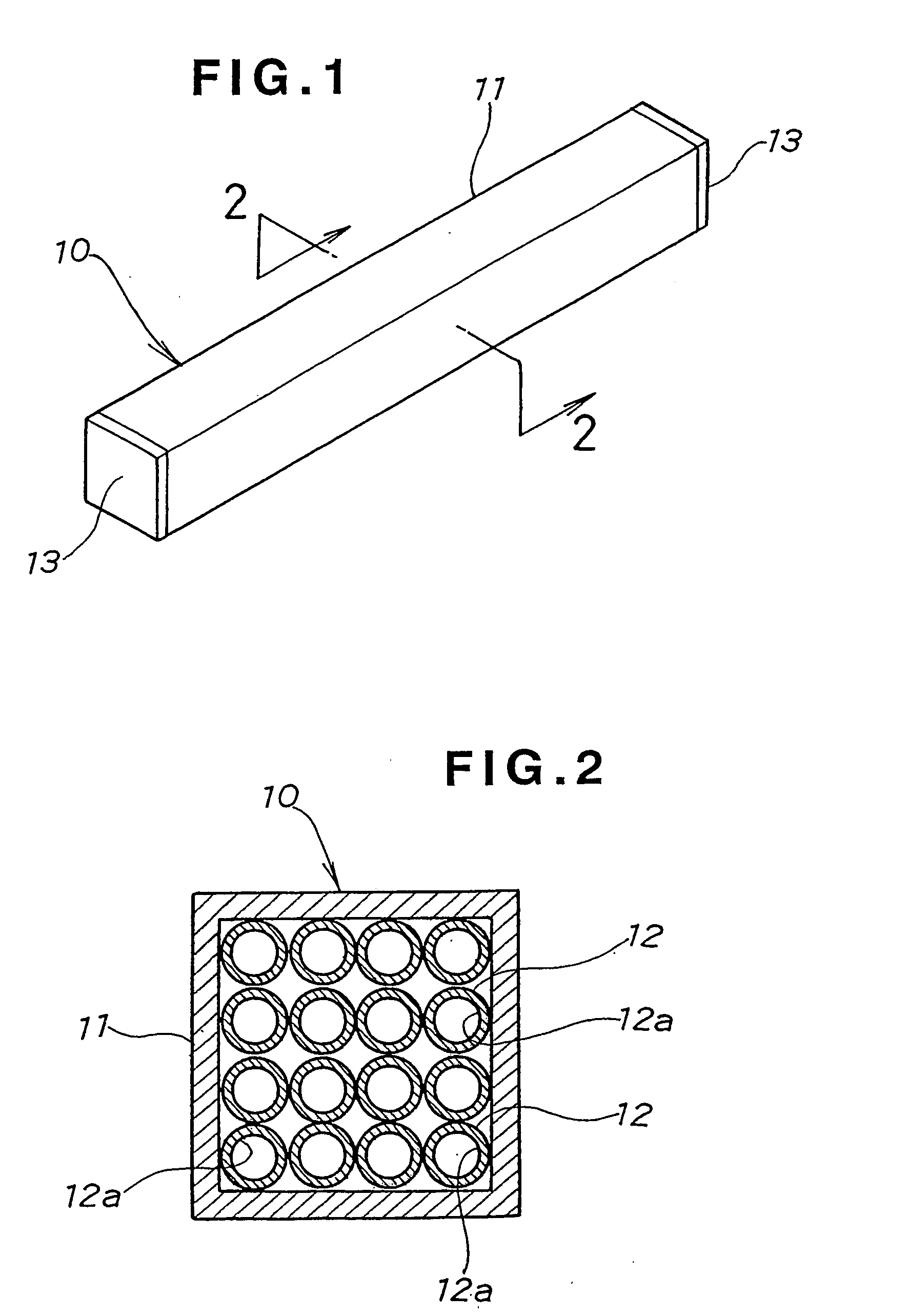
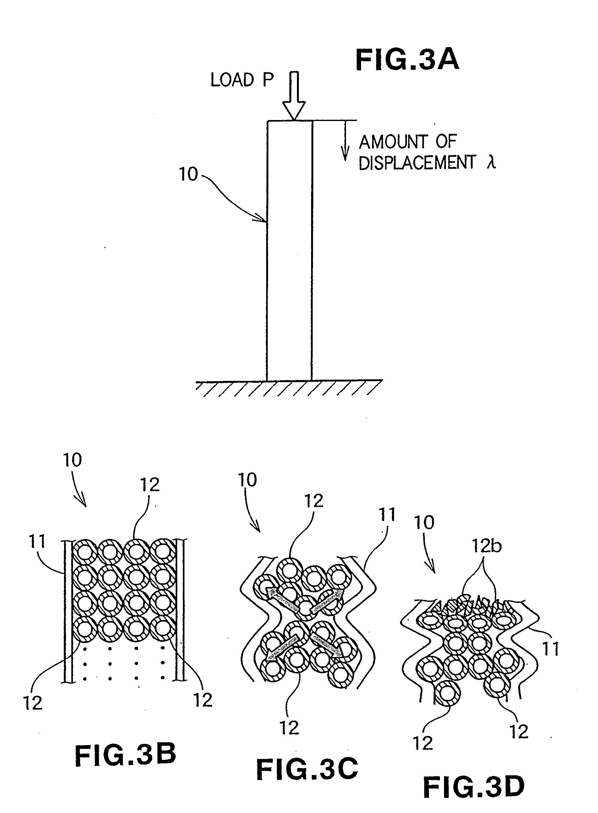
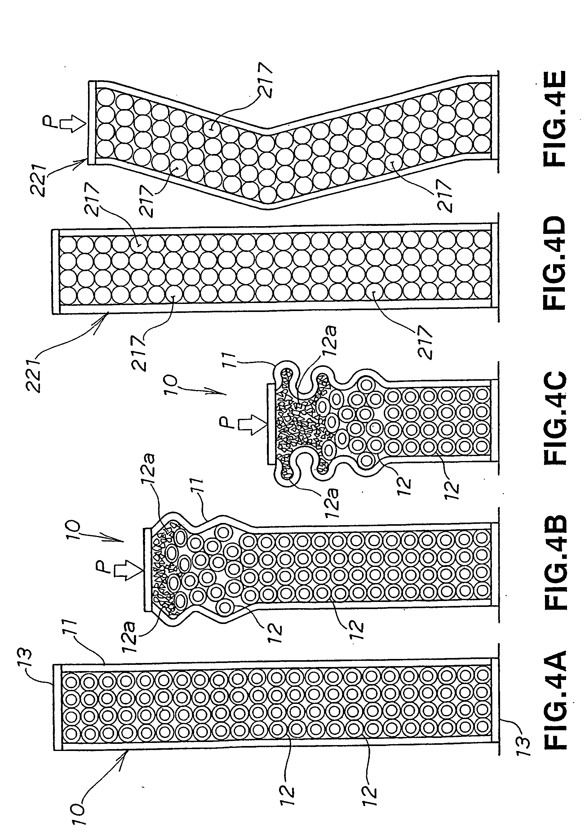
[0063] An increase in the weight of the skeleton member can be restrained by the granular materials having the hollow portions or the porous granular materials. When the skeleton member receives an impact, owing to the frictional force among the granular materials and the deformation or the collapse of the granular materials themselves, the deformation of the skeleton member can be made to proceed gradually from a load-acting side and smoothly while a large load is being generated, whereby far larger impact energy can be absorbed more stable.
[0065] Since the second granular materials are bonded to one another by the hollow first granular materials, the weight of the skeleton member structure can be reduced. In addition, the mutual bonding of the second granular materials can be made firm, and when the skeleton member receives impact, the first granular materials can be collapsed, whereby it is possible to highly efficiently absorb far more impact energy.
[0067] The first granular materials and the second granular materials can be firmly bonded to one another by melting the surfaces of the first granular materials which are hollow and made of a resin, whereby it is possible to form a lightweight large-sized solidified granular material. In addition, the surfaces of the resin-made first granular materials can be melted at a low temperature, whereby the solidified granular material can be easily formed without the need for special equipment.

Problems solved by technology

It can be seen from these graphs that in the range of foaming ratios not higher than a foaming ratio at which a predetermined buckling load b is ensured (in the foamed-material effective area shown in FIG. 20B), the weight becomes large and a reduction in the weight of the structural member becomes difficult.
This is because in each of the samples B and C, since the foamed material or the solid grains are not easily crushed in an early stage of deformation, the internal pressure of the structural member excessively rises and is buckled into a Z-shaped or dogleg-shaped configuration and the load P is sharply decreased by this buckling.
However, for example when an impact acts on a skeleton member, if the deformation of each of the microspheres is small, load occurring in the skeleton member sharply increases, so that impact energy cannot be sufficiently absorbed.
In addition, since special equipment is needed, it is not easy to form the solidified granular material 420.

Method used


Image

  • Skeleton member structure
  • Skeleton member structure
  • Skeleton member structure

Examples


embodiment 2

[0158] The energy absorption efficiency E of each of the embodiment 1 and the embodiment 2 is greatly larger than 1, and exhibits the effect of the hollow granular materials and the porous granular materials.

[0159]FIG. 14 is a graph showing the results of bending tests of structural members according to the invention, and the vertical axis represents the load W which is made to act perpendicularly to the axis of a structural member, while the horizontal axis represents the amount of displacement 6, of the structural member due to the load W.

[0160] As the structural members, there are shown the embodiment 1 (hollow granular materials), the embodiment 2 (porous granular materials), the comparative example 1 (sample A), the comparative example 2 (sample C) and the comparative example 3 (sample B) all of which have been described with reference to FIG. 12.

[0161] In the embodiment 1 and the embodiment 2, it is possible to maintain the large load W at a nearly constant level from an ear...

second embodiment

[0163] Then, a solidified granular material which is disposed to fill a structural member according to the invention will be described with reference to FIGS. 15 to 19.

[0164]FIG. 15 shows a cross-sectional view of a solidified granular material disposed to fill the structural member according to the second embodiment of the invention. This solidified granular material 215 is made of hollow resin-made first granular materials 212 and solid second granular materials 213. Adjacent ones of the second granular materials 213 are bonded to one another by the above-described first granular materials 212. Actually, the first granular materials 212 fill the second granular materials 213 in a nearly dense state, but are coarsely illustrated for the convenience of description.

[0165]FIG. 16 is a magnified view of a solidified granular material according to the second embodiment of the invention. The solidified granular material 215 is a member in which adjacent ones of the second granular mater...

first embodiment

[0174] The second granular materials 213 of the embodiments shown in FIGS. 15, 16, 17A and 17B have been described above with reference to solid granular materials by way of example, but the second granular materials 213 in the invention are not limited to solid granular materials and may also be those shown in FIGS. 11A to 11G as the first embodiment, for example, indefinite porous materials, definite porous materials, star-shaped materials having hollow portions, pipe-shaped materials or spherical granular materials having hollow portions.

[0175] Accordingly, since the second granular materials 213 are formed as hollow or porous granular materials, a further reduction in the weight of the structural member can be realized in combination with the first granular materials 212 (refer to FIG. 15) which bond the second granular materials 213.

[0176] The solidified granular material 215 according to the second embodiment is adopted in the vehicle skeleton structures shown in FIGS. 6A and...


PUM

PropertyMeasurementUnit
structureaaaaaaaaaa
weightaaaaaaaaaa
STRENGTHaaaaaaaaaa

Abstract

A skeleton member structure having a tubular structural member (11, 211) filled with granular materials for absorbing impact energy. The granular materials includes a granular material having a hollow portion (12a, 212a) or a porous granular material. When the skeleton member receives an impact, the granular materials are deformed or collapsed, and impact energy is stably absorbed. Since the granular materials are hollow or porous, the weight of the skeleton member filled with the granular materials is reduced.

Description

TECHNICAL FIELD [0001] This invention relates to a skeleton member structure which is imparted with improved shock absorbing capability without increasing its weight. The invention also relates to a method for forming solidified granular materials. BACKGROUND ART [0002] Skeleton member structures having skeleton or structural members filled with filling materials are know from, for example, (1) paper pre-published for 2001 JSAE (Society of Automotive Engineers of Japan) Spring General Meeting, entitled “ATTEMPT TO COPE WITH BOTH CRASHWORTHINESS AND WEIGHT REDUCTION” (hereinafter called Prior Art 1), (2) science paper, 1986, The university of Manchester, England, “STATIC AND DYNAMIC AXIAL CRUSHING OF FOAM-FILLED SHEET METAL TUBES” (hereinafter called Prior Art 2), (3) paper published in Automobile Engineering, Vol. 55, April, 2001, “DEVELOPMENT OF A METHOD OF ENHANCING BODY FRAME STRENGTH USING STRUCTURAL FOAM” (hereinafter called Prior Art 3), (4) Japanese Patent Laid-Open Publicati...

Claims


Application Information

Patent Timeline
Patent Type & Authority Applications(United States)
IPC IPC(8): B60R99/00F16F7/01F16F7/12
CPCF16F7/121F16F7/015
Inventor YAMAZAKI, SHOUJI
Owner HONDA MOTOR CO LTD
Why Eureka
Try Eureka