

Vehicle driving assisting apparatus
- Summary
- Abstract
- Description
- Claims
- Application Information
AI Technical Summary
Benefits of technology
Problems solved by technology
Method used
Image

Examples
first embodiment
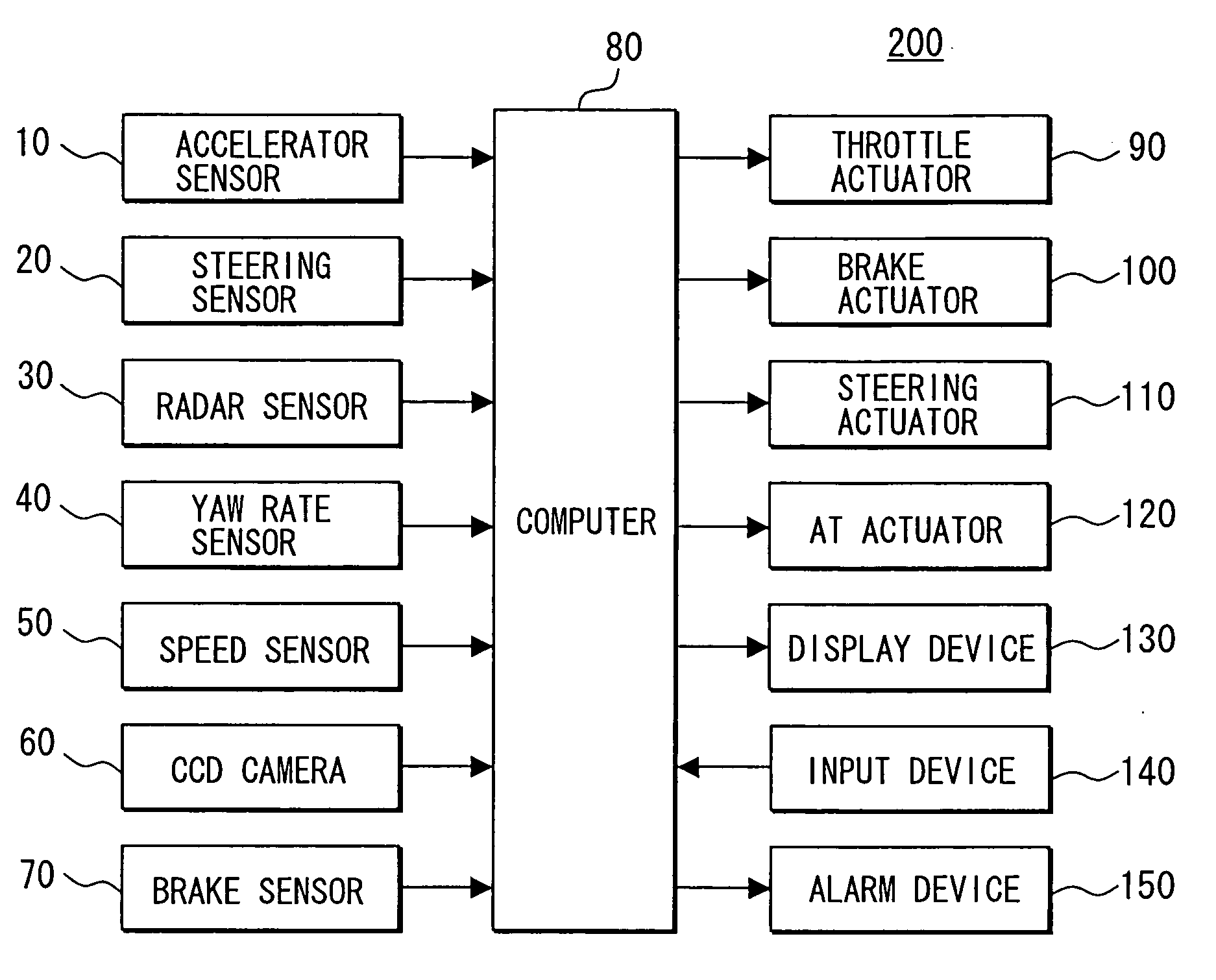
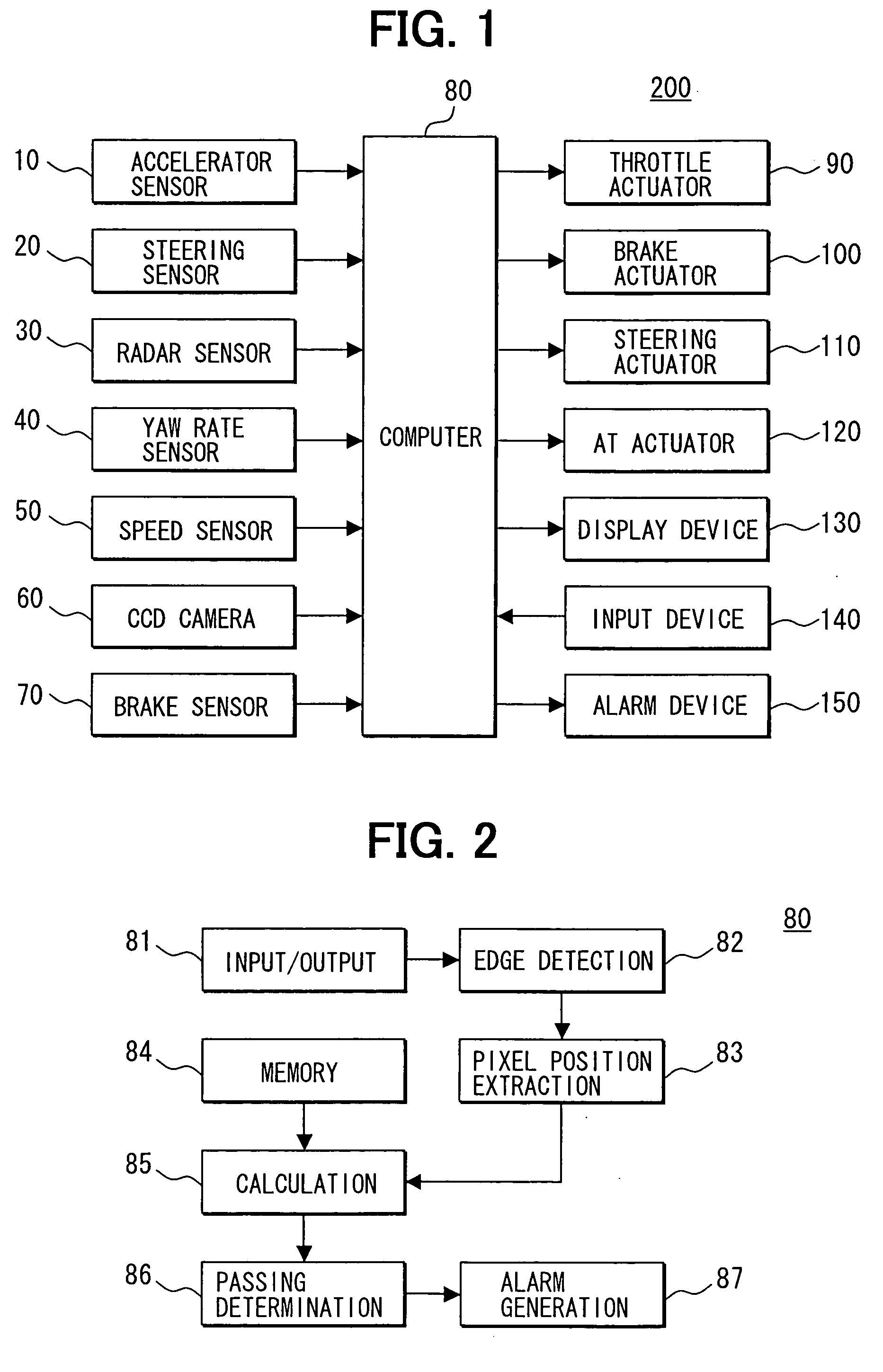
[0053] Referring to FIG. 1, a vehicle driving assisting apparatus 200 includes an accelerator sensor 10, a steering sensor 20, a laser radar sensor 30, a yaw rate sensor 40, a vehicle speed sensor 50, a CCD camera 60 and a brake sensor 70, which are connected to a computer 80.
[0054] The apparatus 200 further includes a throttle actuator 90, a brake actuator 100, a steering actuator 110, an automatic transmission (A / T) actuator 120, a display device 130, an input device 140 and an alarm device 150, which are also connected to the computer 80.
[0055] The computer 80 includes an input / output interface (I / O) and various drive circuits that are not shown. The above hardware constructions are those that are generally known and employed in this kind of apparatus. When the vehicle travels on a narrow road, the computer 80 determines whether the vehicle can pass through, and executes the processing for assisting the driving on a narrow road based on the determined result.
[0056] Based on th...
second embodiment
[0092] The second embodiment of the apparatus 200 is shown in FIG. 13. In this embodiment, the control processing of the computer 80 is divided into the blocks of an input / output unit 81, an image processing unit 82a, a position detection unit 83a, an available width calculation unit 85a, a necessary traveling width memory 84a, a passing determination unit 86 and an alarm generation unit 87.
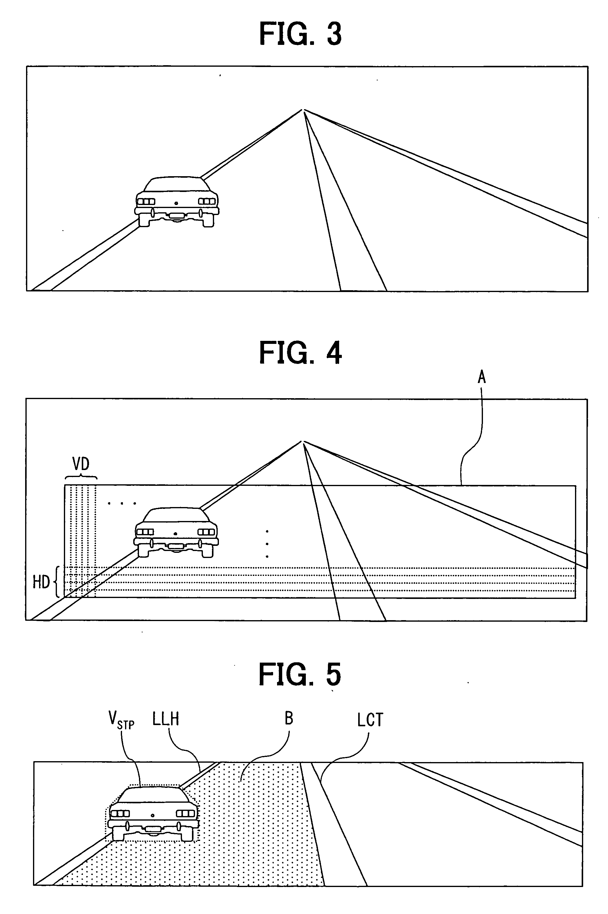
[0093] The image processing unit 82a acquires pixel values only of the pixels in the angle of field in the image that has been preset out of the pixel values of the pixels of the whole image imaged by the CCD camera 60. As the angle of field for acquiring the pixel values, for example, there is set an angle of field A including a vehicle lane from several meters up to several tens of meters in front of the vehicle as shown in FIG. 4, to acquire pixel values only of the pixels on the horizontal lines (HD) and on the vertical lines (VD) in the angle of field A.
[0094] Next, the image processing un...
third embodiment
[0123] In a third embodiment shown in FIG. 20, the control processing of the computer 80 is divided into the blocks of an input / output unit 81, an edge detection unit 82, a pixel position extraction unit 83, a memory 84, a calculation unit 85, a preceding vehicle passing determination unit 89, a vehicle passing determination unit 86 and an alarm generation unit 87. The input / output unit 81 receives signals output from the sensors, and produces signals that are processed by the computer 80 and that are to be output.
[0124] First, the edge detection unit 82 acquires pixel values only of the pixels in the angle of field in an image that has been preset out of the pixel values of the pixels of the whole image imaged by the CCD camera 60. As an angle of field for acquiring the pixel values, for example, an angle of field A is set as shown in FIG. 22 to include a vehicle lane from several meters up to several tens of meters in front of the vehicle. This is for acquiring pixel values of th...
PUM
 Abstract
Description
Claims
Application Information