Storage control apparatus and storage control method

a storage control and control apparatus technology, applied in the field of remote copying techniques, can solve problems such as large transfer overhead, and achieve the effect of suppressing the degradation of response performance and suppressing the overhead of data transfer between a cpu and a disk system

Inactive Publication Date: 2005-06-09
HITACHI LTD
View PDF18 Cites 29 Cited by
  • Summary
  • Abstract
  • Description
  • Claims
  • Application Information

AI Technical Summary

Benefits of technology

[0016] When a remote copy is performed between disk systems at remote sites, the write request is transferred directly between the disk systems so that the data transfer overhead between a CPU and a disk system can be suppressed. Further, it is possible to suppress degradation of the response performance that the primary CPU issues a write request to the primary disk system ...

Problems solved by technology

However, since the primary CPU is required to read a write request and transfer data to the secondary ...

Method used


Image

  • Storage control apparatus and storage control method
  • Storage control apparatus and storage control method
  • Storage control apparatus and storage control method

Examples


first embodiment

[0032] First, the first embodiment will be described.

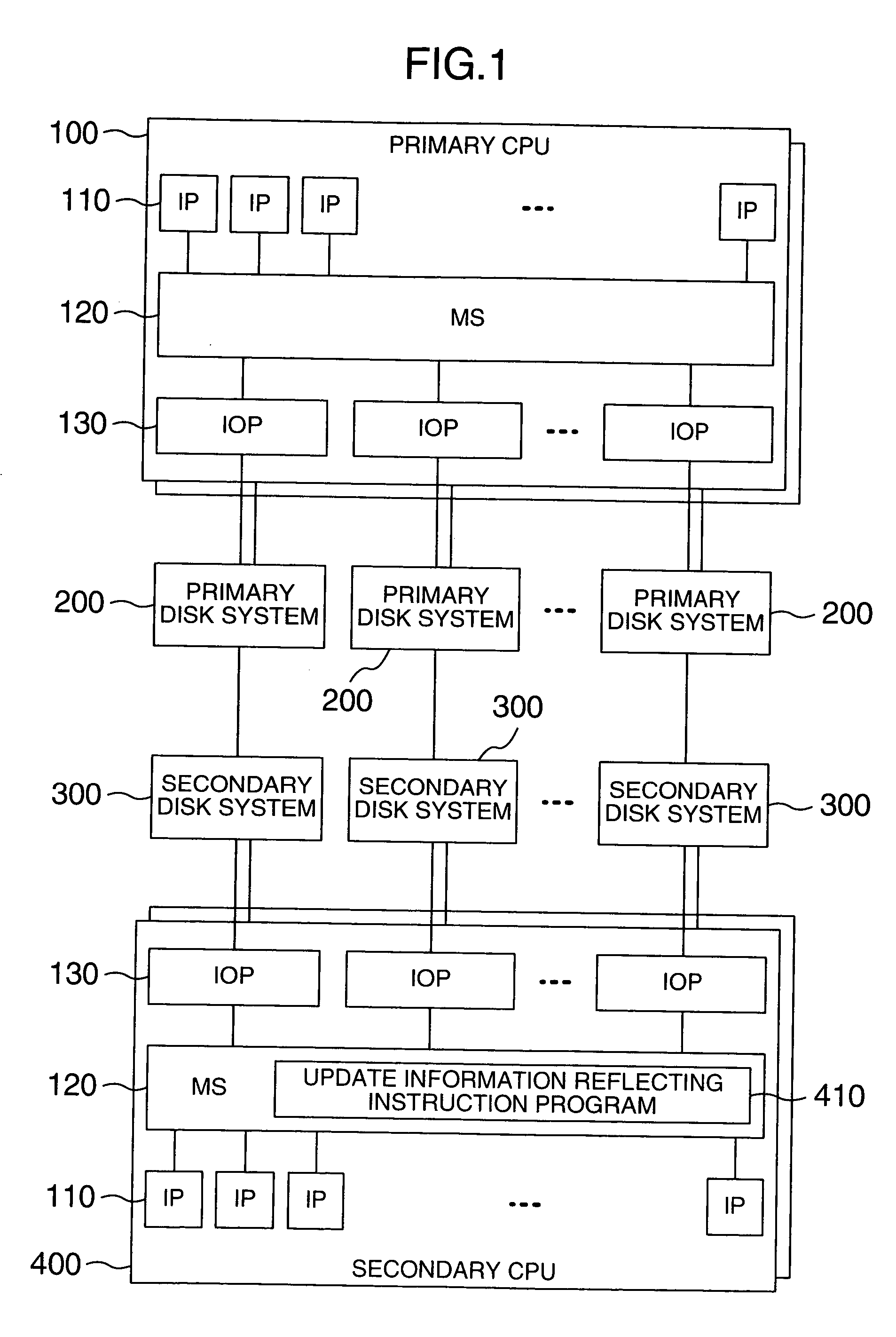
[0033]FIG. 1 is a diagram showing the whole configuration of a system according to the first embodiment.

[0034] A computer (hereinafter called a primary CPU) 100 has one main storage (hereinafter called an MS) 120, one or a plurality of instruction processors (hereinafter called an IP) 110 connected to MS 120, and one or a plurality of input / output processors (hereinafter called an IOP) 130 connected to MS 120. One or a plurality of disk systems (hereinafter called primary disk systems) 200 are connected to one or a plurality of primary CPUs 100 via IOPs 130. Each primary disk system 200 is connected to a corresponding disk system (hereinafter called a secondary disk system) 300. Each secondary disk system 300 is connected to one or a plurality of computers (hereinafter called secondary CPUs) 400. The hardware structure of the secondary CPU 400 is similar to that of the primary CPU 100, and has one or a plurality of IPs 110 and a...

second embodiment

[0061] Next, the second embodiment will be described.

[0062] In the first embodiment, as the standard time which is supplied by the update information reflecting instruction program 410 to the secondary disk system 300, the time stored in the secondary update information storing unit 350, i.e., the past time, is used. In this case, the update information reflecting instruction program 410 first collects the latest times of update information from all secondary disk systems 300 and sets the oldest time among them as the standard time. Two instructions are therefore required to be supplied to each secondary disk system 300 in order to designate one standard time. In the second embodiment, a future time is used as the standard time so that one instruction is made for each secondary disk system 300. In the second embodiment, only different points from the first embodiment will be described. The constituent elements and flow charts other than the description of the second embodiment are ...

third embodiment

[0078] Next, the third embodiment will be described.

[0079] In the first embodiment, if the update information is stored in the primary update information storage unit 250 in the primary disk system 200, the update information transmitting unit 230 of the primary disk system transmits the update information to the secondary disk system 300. Namely, the primary disk system 200 has the initiative in transferring the update information. The third embodiment discloses the arrangement that the secondary disk control unit 310 has the initiative in transferring the update information. In the third embodiment, only different points from the first embodiment will be described. The constituent elements and flow charts other than the description of the third embodiment are the same as those of the first embodiment.

[0080] The different point of the configuration of the primary disk system 200 of the third embodiment from the configuration of the primary disk system 200 of the first embodiment ...


PUM


Abstract

A storage control apparatus and a storage control method are provided wherein in a system having a plurality of disk systems and secondary disk systems at remote sites, the data transfer amount between a central processing unit and a disk system can be reduced when duplicate disk write is performed, the performance can be prevented from being degraded even if the distance between control units is elongated, and the intermediate results of a transaction are not left. A standard time is determined and a program is provided which instructs a secondary central processing unit to reflect only update information having a write time older than the standard time, upon a logical disk in the secondary disk system.

Description

BACKGROUND OF THE INVENTION [0001] 1. Field of the Invention [0002] The present invention relates to techniques of remote copy between different disk systems. [0003] 2. Description of the Related Art [0004] The specification of European Patent Publication No. 0672985 discloses techniques of writing remote copy between disk systems at remote sites. According to the specification of European Patent Publication No. 0672985, a primary disk system receiving a write request directly from a computer (hereinafter called a primary CPU) executing an application, reports a write request completion to the primary CPU immediately after the write request process. Further, a copy of the write request received at the primary disk system is read by the primary CPU. A write request issued from the primary CPU includes a time when the primary CPU issued the write request. When the copy of the write request is read by the primary CPU, the write time is also passed to the primary CPU. The read copy of t...

Claims


Application Information

Patent Timeline
IPC IPC(8): G06F11/16G06F3/06G06F11/20G06F12/00
CPCG06F11/2064Y10S707/99955Y10S707/99953G06F11/2071
Inventor NINOSE, KENTAARAKAWA, HIROSHIASAKA, YOSHIHIROHIRAKAWA, YUSUKE
Owner HITACHI LTD
Why Eureka
Try Eureka