Refrigerant cycle apparatus

a technology of refrigerant cycle and cycle body, which is applied in the direction of lighting and heating apparatus, positive displacement liquid engine, liquid fuel engine, etc., can solve the problems of durability and run efficiency drop, low refrigerant pressure on the low-pressure side, etc., and achieves low cost and low cost. , the effect of quickly eliminating the reverse phenomenon

Inactive Publication Date: 2005-06-16
SANYO ELECTRIC CO LTD
View PDF4 Cites 10 Cited by
  • Summary
  • Abstract
  • Description
  • Claims
  • Application Information

AI Technical Summary

Benefits of technology

[0018] Moreover, the discharge refrigerant pressure of the first compression element changes in association with the discharge refrigerant temperature. In the present invention, the temperature sensor for detecting the discharge refrigerant temperature of the first compression element, and the control device into which the output of the temperature sensor is input detect the reverse of the discharge refrigerant pressures of the first and second compression elements based on the discharge refrigerant temperature of the first compression element. Therefore, for example, when the discharge refrigerant temperature of the first compression element rises to the predetermined value, it is judged that the discharge refrigerant pressures of the first and second compression elements are reversed. Accordingly, the pressure reverse phenomenon in the first and second compression elements can be detected by use of the existing temperature sensor at a low cost without disposing any special pressure sensor.
[0019] Furthermore, in the present invention, the first sensor for detecting the discharge refrigerant pressure of the first compression element, the second sensor for detecting the discharge refrigerant pressure of the second compression element, and the control device into which the outputs of both the sensors are input detect the reverse of the discharge refrigerant pressures of the first and second compression elements based on the discharge refrigerant pressures of the first and second compression elements. Therefore, the pressure reverse phenomenon in the first and second compression elements can be securely detected.
[0020] Additionally, the discharge refrigerant pressures of the first and second compression elements similarly change in association with the dis...

Problems solved by technology

Therefore, even when the rotary compressor starts, the refrigerant pressure on the low-pressure side does not easily drop.
When this pressure reverse occurs, ...

Method used


Image

  • Refrigerant cycle apparatus
  • Refrigerant cycle apparatus
  • Refrigerant cycle apparatus

Examples


Embodiment Construction

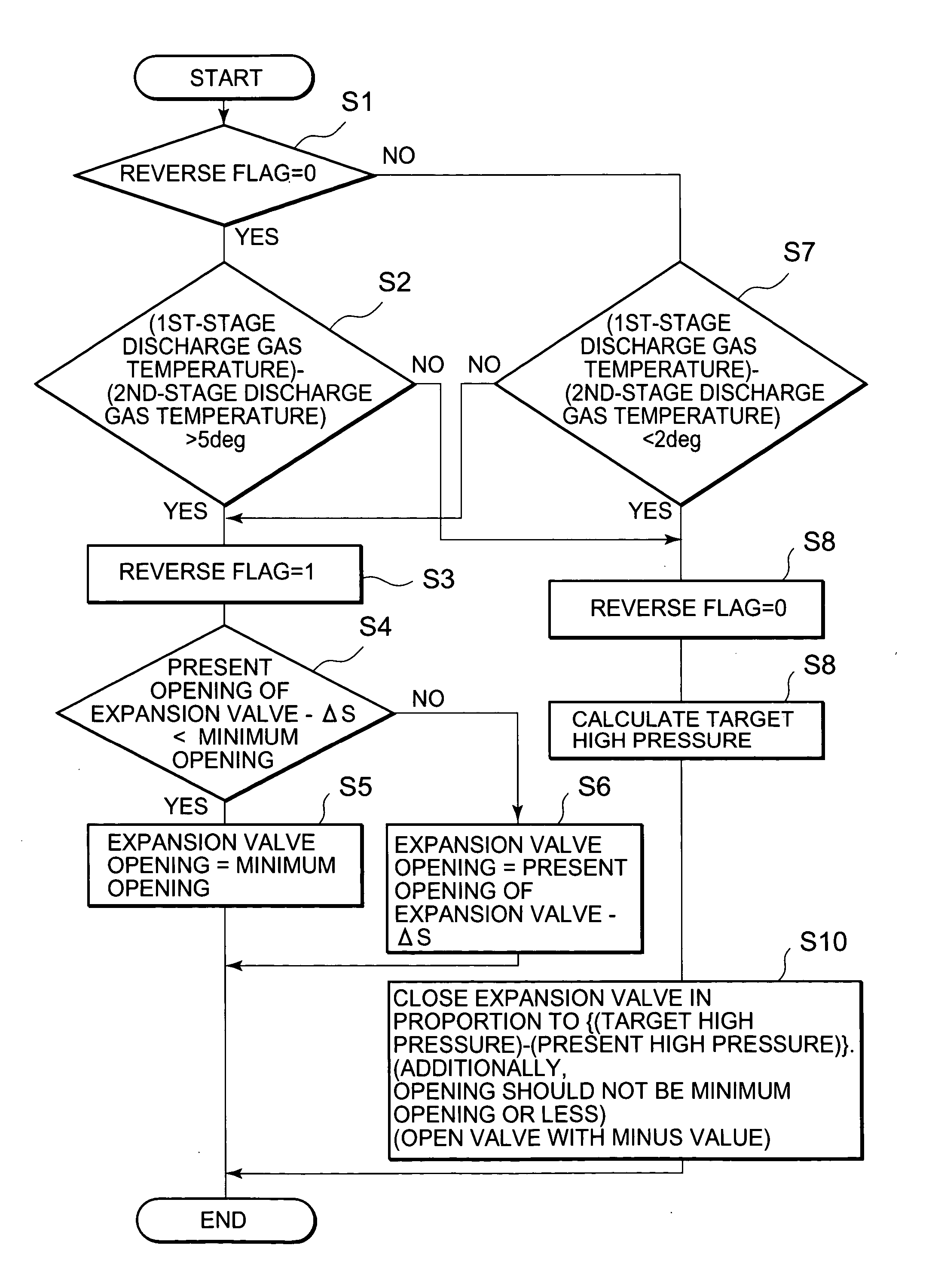
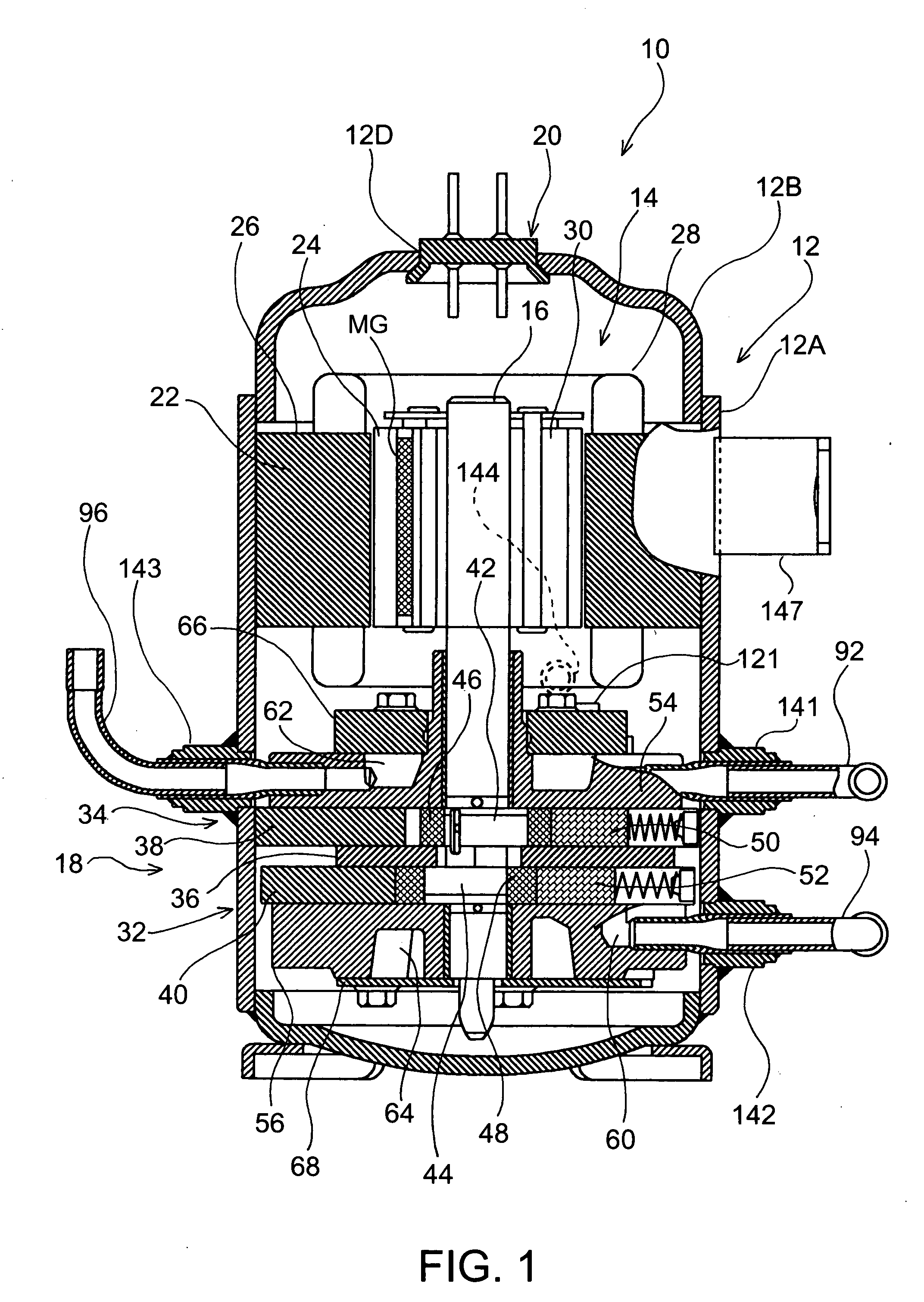
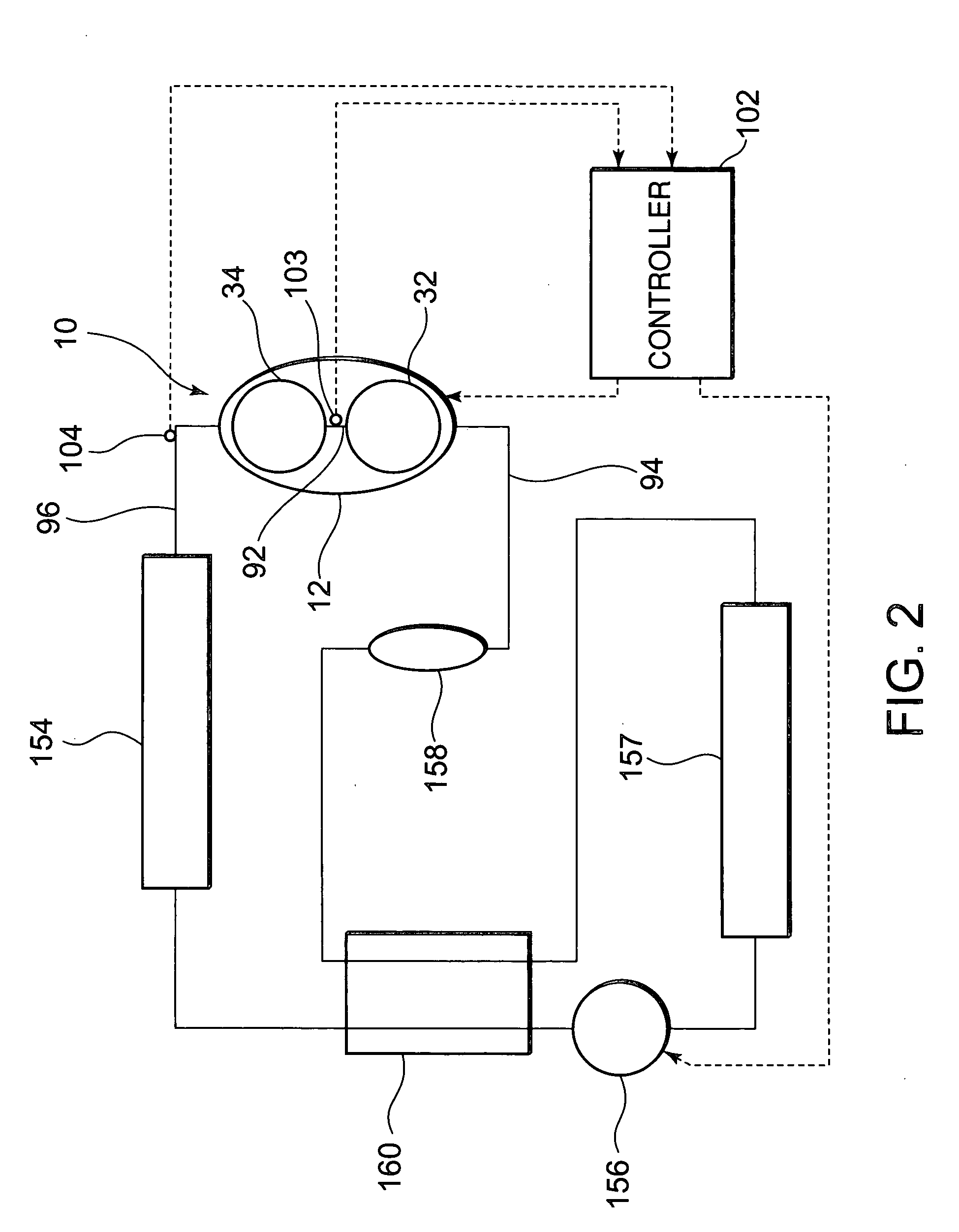
[0026] An embodiment of the present invention will be described hereinafter in detail with reference to the drawings. FIG. 1 is a vertical sectional view of an internal intermediate pressure type multistage (two-stage) compression system rotary compressor 10 including first and second rotary compression elements 32, 34 (either is one example of the compression element), which is an example of the compressor for use in a refrigerant cycle apparatus of the present invention. It is to be noted that the refrigerant cycle apparatus of the embodiment is supercritical on a high-pressure side.

[0027] In this figure, reference numeral 10 denotes the internal intermediate pressure type multistage compression system rotary compressor (corresponding to the compressor of the present invention) in which carbon dioxide (CO2) is used as a refrigerant. The rotary compressor 10 comprises: a cylindrical airtight container 12 formed of a steel plate; an electromotive element 14 disposed / stored on an ...


PUM


Abstract

For a purpose of realizing a refrigerant cycle apparatus capable of exactly detecting a pressure reverse phenomenon caused in a compression element of a compressor of a multistage compression type, in the refrigerant cycle apparatus in which the multistage compression type compressor constitutes a refrigerant circuit, including an electromotive element, and first and second compression elements driven by the electromotive element in an airtight container to suck an intermediate-pressure refrigerant gas compressed by the first compression element into the second compression element and to compress and discharge the refrigerant gas, the apparatus comprising: a sensor for detecting a discharge refrigerant pressure of the first compression element; and a control device into which an output of the sensor is input, the control device detects reverse of the discharge refrigerant pressures of the first and second compression elements based on the discharge refrigerant pressure of the first compression element.

Description

BACKGROUND OF THE INVENTION [0001] The present invention relates to a refrigerant cycle apparatus in which a multistage compression type compressor constitutes a refrigerant circuit including an electromotive element and first and second compression elements driven by the electromotive element in an airtight container to suck an intermediate-pressure refrigerant gas compressed by the first compression element into the second compression element and to compress and discharge the gas. [0002] For example, a two-stage compression type rotary compressor has heretofore comprised an electromotive element including a stator and rotor (the number of revolutions are controlled by an inverter), a first rotary compression element driven by the electromotive element, and a second rotary compression element attached via a phase difference of 180 degrees, which are stored in an airtight container (see Japanese Patent Application Laid-Open No. 2-294587, for example). [0003] Moreover, a refrigerant ...

Claims


Application Information

Patent Timeline
IPC IPC(8): F04C23/00F04C18/356F04C28/08F04C28/28F25B1/00F25B1/10F25B9/00F25B40/00
CPCF04C18/3564Y02B30/741F04C28/08F04C28/28F04C2270/18F04C2270/86F25B1/10F25B9/008F25B40/00F25B2309/061F25B2500/26F25B2600/021F25B2600/2513F25B2700/1931F25B2700/21152F04C23/001Y02B30/70A46B5/0091A46B13/026A46B2200/1066
Inventor EBARA, TOSHIYUKIKUBO, MAMORUOTAGAKI, KAZUHISA
Owner SANYO ELECTRIC CO LTD
Why Eureka
Try Eureka