
Swash plate drive system

a technology of drive system and swash plate, which is applied in the direction of reciprocating piston engine, positive displacement liquid engine, positive displacement engine, etc., can solve the problems of wear and metal fatigue in the swash plate and associated structure, and achieve the effect of reducing wear and metal fatigu

Active Publication Date: 2005-06-16
RIX INDS
View PDF4 Cites 5 Cited by
  • Summary
  • Abstract
  • Description
  • Claims
  • Application Information

AI Technical Summary

Benefits of technology

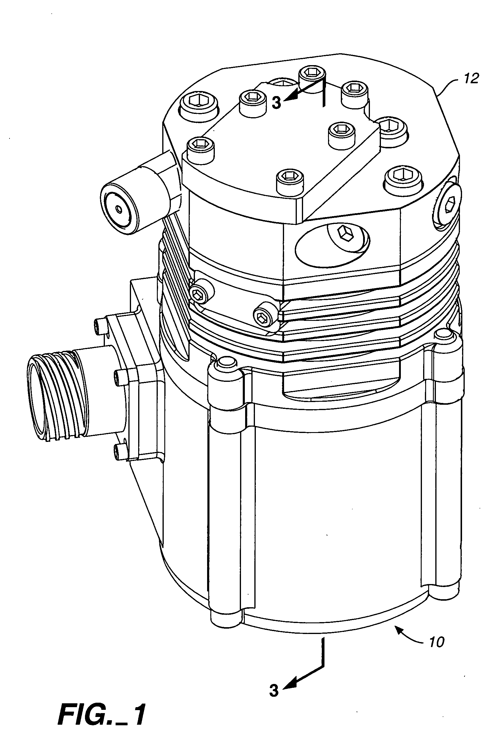
[0004] The present invention relates to a unique approach for converting rotary motion into reciprocating motion. The arrangement eliminates the need for an anti-rotation means for the swash plate, allowing different locations on the contact surface of the swash plate to be engaged during operation. This greatly reduces wear and metal fatigue at the contact points. Also, the apparatus of the present invention eliminates the need for a connecting rod or other interconnecting structure between the swash plate and reciprocating members at fixed locations thereon.

Problems solved by technology

Such arrangements produce wear and metal fatigue in the swash plate and associated structure.

Method used


Image

  • Swash plate drive system
  • Swash plate drive system
  • Swash plate drive system

Examples


Embodiment Construction

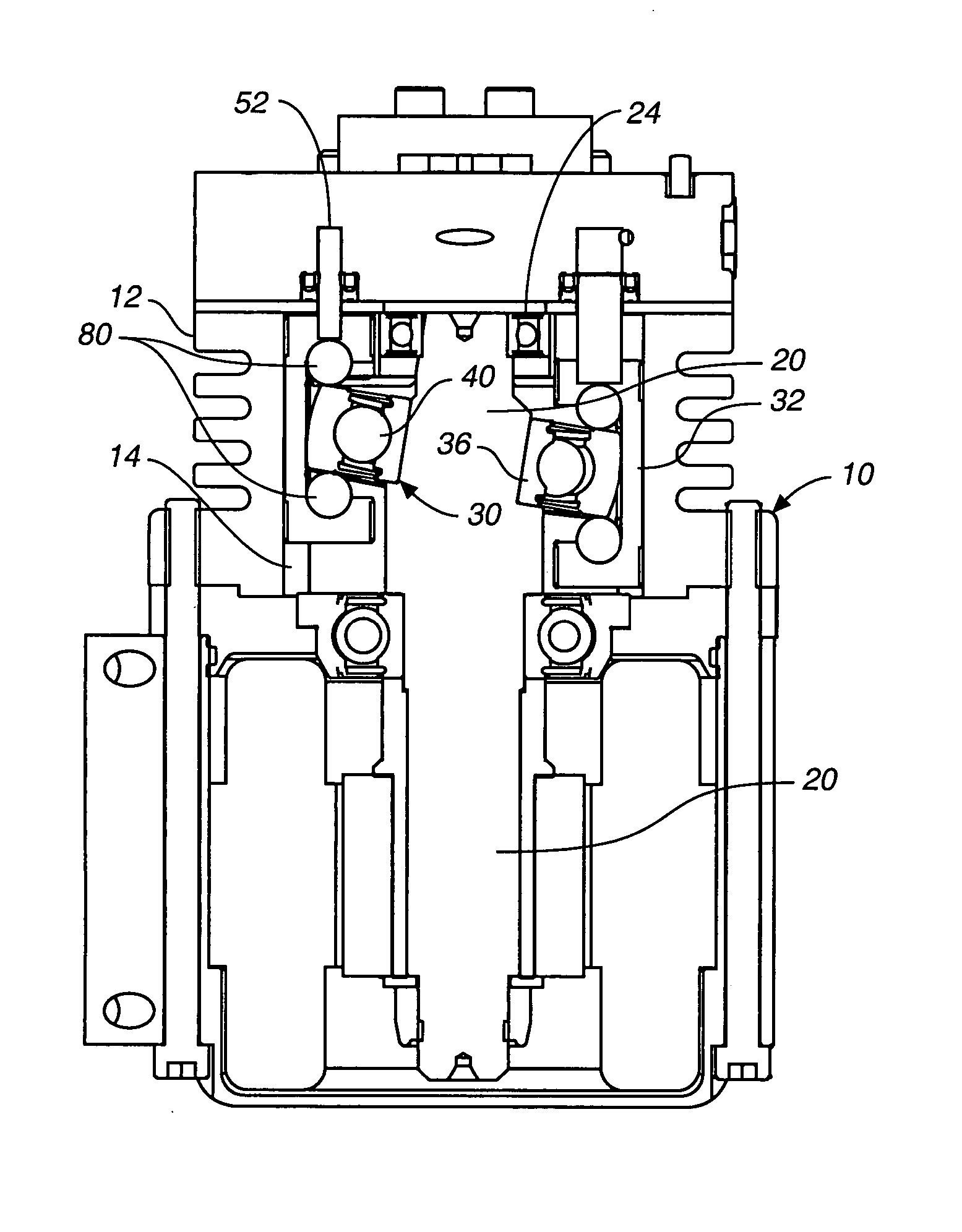
[0015] Referring now to the drawings, an air compressor 10 incorporating the present invention is illustrated, the compressor having a housing 12 defining a housing interior 14.

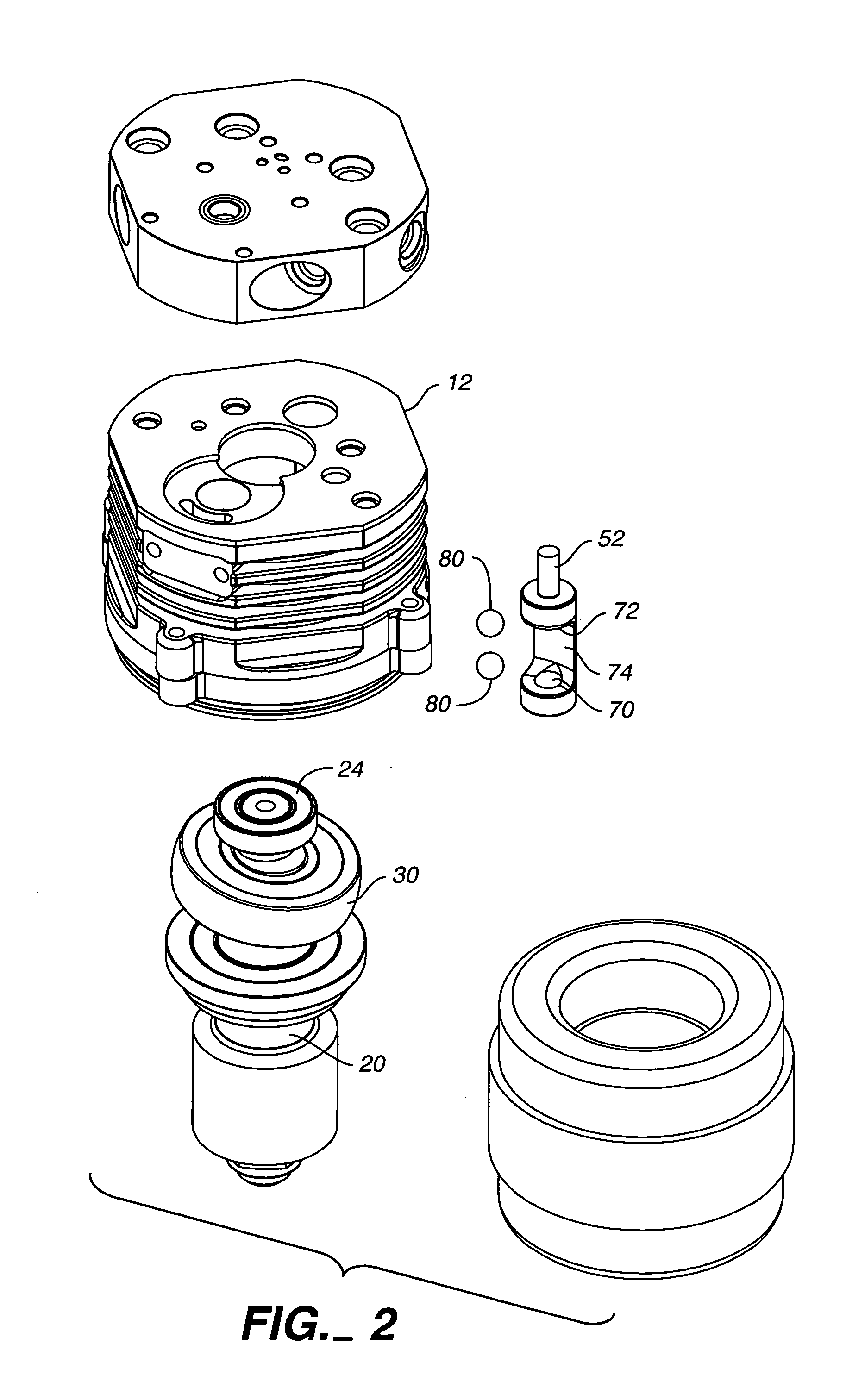
[0016] A swash plate drive shaft 20 is disposed in the housing interior and rotatably mounted relative to the housing by a motor of the compressor about an axis of rotation A (see FIG. 4). A portion 22 of the drive shaft is canted, i.e. angularly oriented relative to axis of rotation A. Bearings such as ball bearing 24 are disposed about the drive shaft to rotatably support the drive shaft relative to the compressor housing.

[0017] A swash plate 30 in the form of a ball bearing assembly is mounted on the swash plate drive shaft and angularly disposed relative to axis of rotation A, the swash plate being located in housing interior 14.

[0018] The outer swash plate portion of the ball bearing assembly comprising the swash plate is in the form of an outer ball bearing assembly race 32. The ball bearing assembly...


PUM


Abstract

A swash plate disposed in a housing is a ball bearing assembly. The outer race of the ball bearing assembly is free to move relative to a swash plate drive shaft and also relative to reciprocating members driven by the swash plate and mounted for axial movement.

Description

TECHNICAL FIELD [0001] This invention relates to swash plate drive apparatus. The invention is applicable, for example, for use in compressors. However, the invention can be utilized in and with equipment other than compressors. BACKGROUND OF THE INVENTION [0002] The use of swash plates in compressors and other types of equipment is well known. Swash plates convert rotary motion into reciprocating motion imparted to pistons or other members. [0003] In conventional swash plate arrangements, it is standard practice to provide structure preventing rotation of the swash plate and provide mechanical linkages, such as connector rods, between the non-rotating swash plate and pistons or other reciprocating members actuated thereby. Such arrangements produce wear and metal fatigue in the swash plate and associated structure. DISCLOSURE OF INVENTION [0004] The present invention relates to a unique approach for converting rotary motion into reciprocating motion. The arrangement eliminates the ...

Claims


Application Information

Patent Timeline
Patent Type & Authority Applications(United States)
IPC IPC(8): F01B3/00F01B3/02F01B13/04F04B1/12F04B27/08F04B27/10
CPCF01B3/0023F01B3/0026F04B27/1054F04B27/0895F01B3/02
Inventor BELOW, JOHN
Owner RIX INDS
Learn More