Low drag ship hull

a low-drag, hull technology, applied in the field of hydrodynamics, can solve the problems of significant reduction and remains of wetted surface area, and achieve the effect of reducing drag and motion in waves

Active Publication Date: 2005-06-16
LANG THOMAS G +1
View PDF45 Cites 43 Cited by
  • Summary
  • Abstract
  • Description
  • Claims
  • Application Information

AI Technical Summary

Benefits of technology

[0006] The low drag hull of the present invention uses air cavities to significantly reduce hull drag. This invention applies to most types and sizes of ships and boats. Its advantages include a large savings in fuel and vessel costs, and improvements in range, speed, payload, sea kindliness, and quietness. Applications for this invention include military, other government, state, commercial, and recreational uses.

Problems solved by technology

Although drag is significantly reduced by SES craft, considerable wetted surface area remains, together with significant wavemaking drag and other sources of drag including the drag of side fences.
The problem is how to design underwater surfaces to make full use of air cavities to minimize wetted surface area and maximize drag reduction.

Method used


Image

  • Low drag ship hull
  • Low drag ship hull
  • Low drag ship hull

Examples


Embodiment Construction

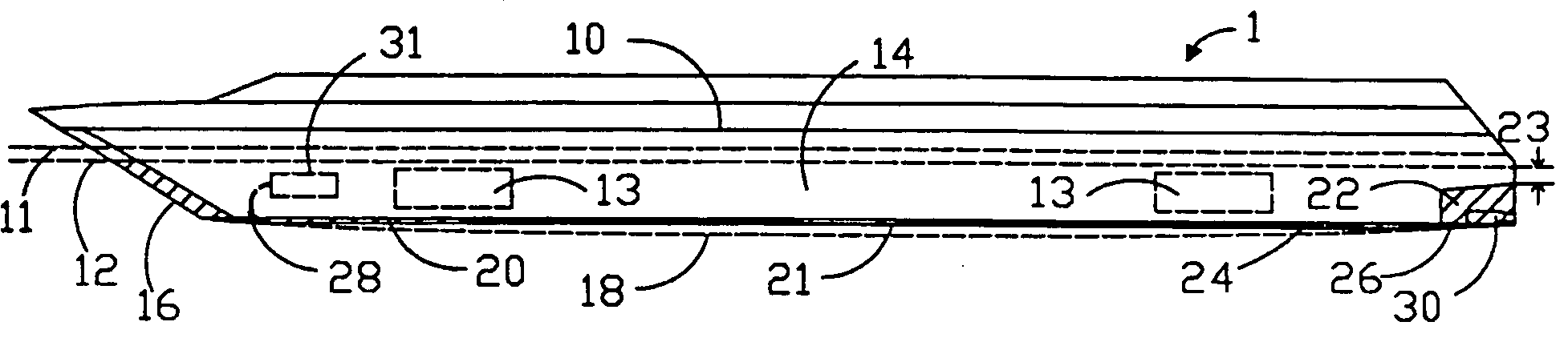
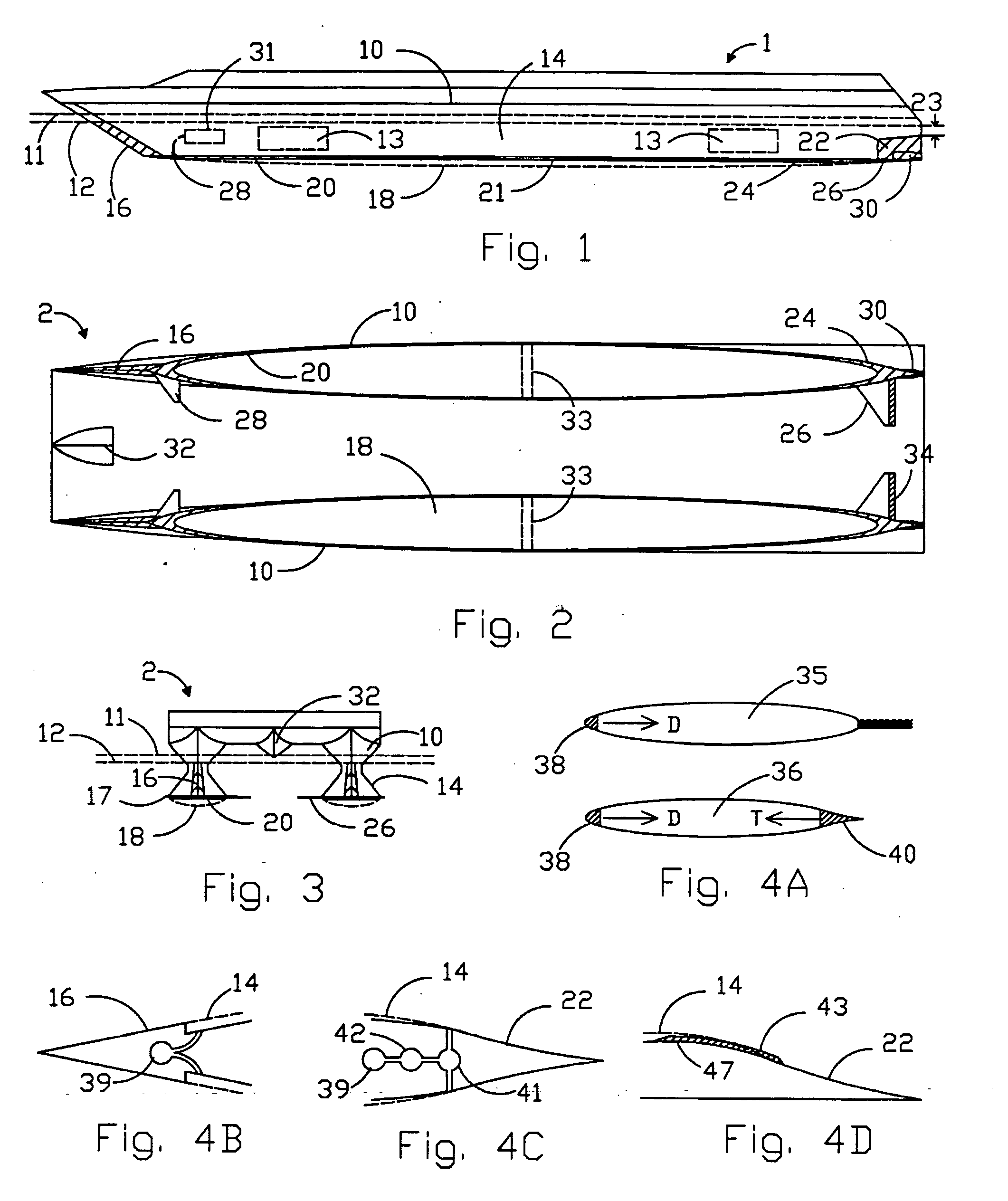
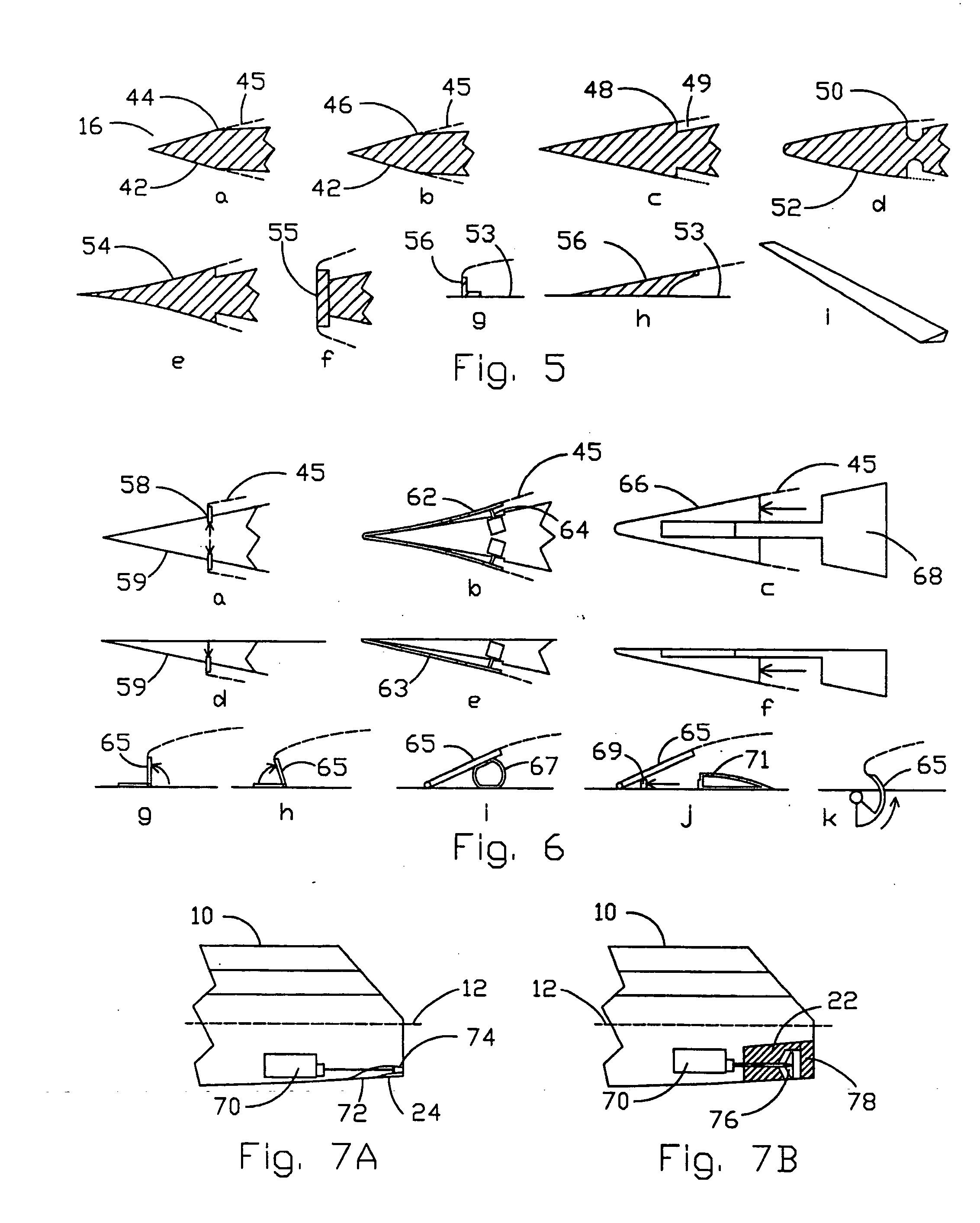
[0091] A low drag ship hull generally includes a side air cavity initiated by a wetted bow section, bottom air cavity initiated by a wetted bottom nosepiece, wetted stem section that closes a lower portion of the side cavity, wetted bottom tailpiece that closes the bottom cavity, stabilizing fin, canard fin, and propulsor. The cross structure of the catamaran hull includes a bow impact alleviator. Optional flaps in the stabilizing fins, together with optional all-movable canard fins or canard fins with flaps, are used for control. Different wetted bow sections and retractable means are used for starting side cavities. A low drag hull may utilize multiple cavities to maximize cavity coverage under off-design conditions, reduce beam, and help in other ways. A new low drag hull includes a new upper bottom air cavity that is initiated by an upper bottom wetted nosepiece,-and closed by an upper bottom tailpiece. An alternative design has a new, shortened forward hull spaced ahead of a sh...


PUM


Abstract

A low drag ship hull generally includes a side air cavity initiated by wetted bow section, bottom air cavity initiated by wetted bottom nosepiece, wetted stem section that closes a lower portion of the side cavity, wetted bottom tailpiece that closes the bottom cavity, stabilizing fin, and propulsor. The bottom of a catamaran hull cross structure includes bow impact alleviator. Optional flaps in the stabilizing fins, together with optional all-movable canard fins are used for control. Different wetted bow sections and retractable means are used for starting side cavities. A low drag hull may utilize multiple air cavities. A new low drag hull includes a new upper bottom air cavity that is initiated by an upper bottom wetted nosepiece, and closed by an upper bottom tailpiece. Alternative designs include a shortened forward hull spaced ahead of a shortened aft hull, and a hydrofoil-supported trimaran with low drag hulls.

Description

BACKGROUND OF THE INVENTION [0001] This invention applies to the field of hydrodynamics, and relates to the use of gas cavities to reduce the frictional drag of ship hulls. [0002] The reduction of frictional drag provides basic benefits: power is reduced, and fuel consumption is reduced. These benefits reduce the weight of a vessel, which further reduces power and fuel consumption compared with a fully wetted vessel designed for a given payload and range. Alternatively, vessel speed can be significantly increased with the same displacement, power, payload and range. Cost and time for payload delivery are greatly reduced by reducing drag. [0003] Past work on the use air cavities to reduce hull drag includes different kinds of surface effect ships (SES). These vessels use a pocket of compressed air on the underside of a vessel to support the weight of the vessel and reduce frictional drag. SES design speeds range from low to very high. Some SES vessels resemble conventional ships with...

Claims


Application Information

Patent Timeline
Patent Type & Authority Applications(United States)
IPC IPC(8): B63B1/04B63B1/06B63B1/10B63B1/12B63B1/18B63B1/24B63B1/32B63B1/34B63B1/38B63G8/00B63G8/18
CPCB63B1/18B63B1/24B63B1/32B63B39/06Y02T70/12Y02T70/122B63B1/38Y02T70/10B63B34/40B63B1/34
Inventor LANG, THOMAS G.LANG, JAMES T.
Owner LANG THOMAS G
Why Eureka
Try Eureka