Methods of hydrogen cleaning of metallic surfaces

a technology for cleaning metallic surfaces and hydrogen, applied in the direction of cleaning processes and equipment, cleaning liquids, lighting and heating equipment, etc., can solve the problems of low-productivity methods requiring substantial manual labor, not providing dynamic hydrogen gas flow, and developing surface contaminants including surface oxides and surface cracks

Active Publication Date: 2005-06-16
GENERAL ELECTRIC CO
View PDF10 Cites 23 Cited by
  • Summary
  • Abstract
  • Description
  • Claims
  • Application Information

AI Technical Summary

Benefits of technology

[0004] In accordance with a preferred aspect of the present invention, the metallic surfaces, for example, the surfaces of turbine components formed of cobalt-based alloys, stainless steels or mild steels, are cleaned using pulsed hydrogen gas. Particularly, the heated component(s) disposed in a vacuum furnace is subjected at temperature to repetitive cycling of a hydrogen gas and a vacuum within the vacuum furnace by supplying in each cycle a fresh supply of hydrogen gas within the furnace, followed by a vacuum. In each cycle, the vacuum removes reaction products between the hydrogen gas and the surface components and any residual hydrogen gas from within the vacuum furnace. The repetitive cycling or pulsing of the hydrogen atmosphere enables multiple successive evacuation of the reaction products that form between the hydrogen gas and surface oxides / contaminants, particularly in the surface cracks, and also enables a fresh supply of hydrogen to be reintroduced to the surfaces and particularly the tight crack surfaces of the component. This reintroduction of hydrogen gas allows the chemical reaction to proceed with fresh activation in regions that have previously been evacuated and are difficult to access and maintain contact with fresh hydrogen gas.

Problems solved by technology

Metallic components, for example, turbine components, particularly turbine nozzles formed of cobalt alloys, develop surface contaminants including surface oxides and surface cracks during usage over time and require refurbishing.
Those methods, however, are low-productivity methods requiring substantial manual labor.
Both of these prior methods, however, do not provide dynamic hydrogen gas flow into tight cracks and the hydrogen gas becomes depleted over time, resulting in no further reduction of oxides.
As a consequence, the metallic surfaces are not sufficiently cleaned, which thereby inhibits the adherence of a fresh filler of molten metal e.g., using the ADH process.

Method used


Image

  • Methods of hydrogen cleaning of metallic surfaces
  • Methods of hydrogen cleaning of metallic surfaces

Examples


Embodiment Construction

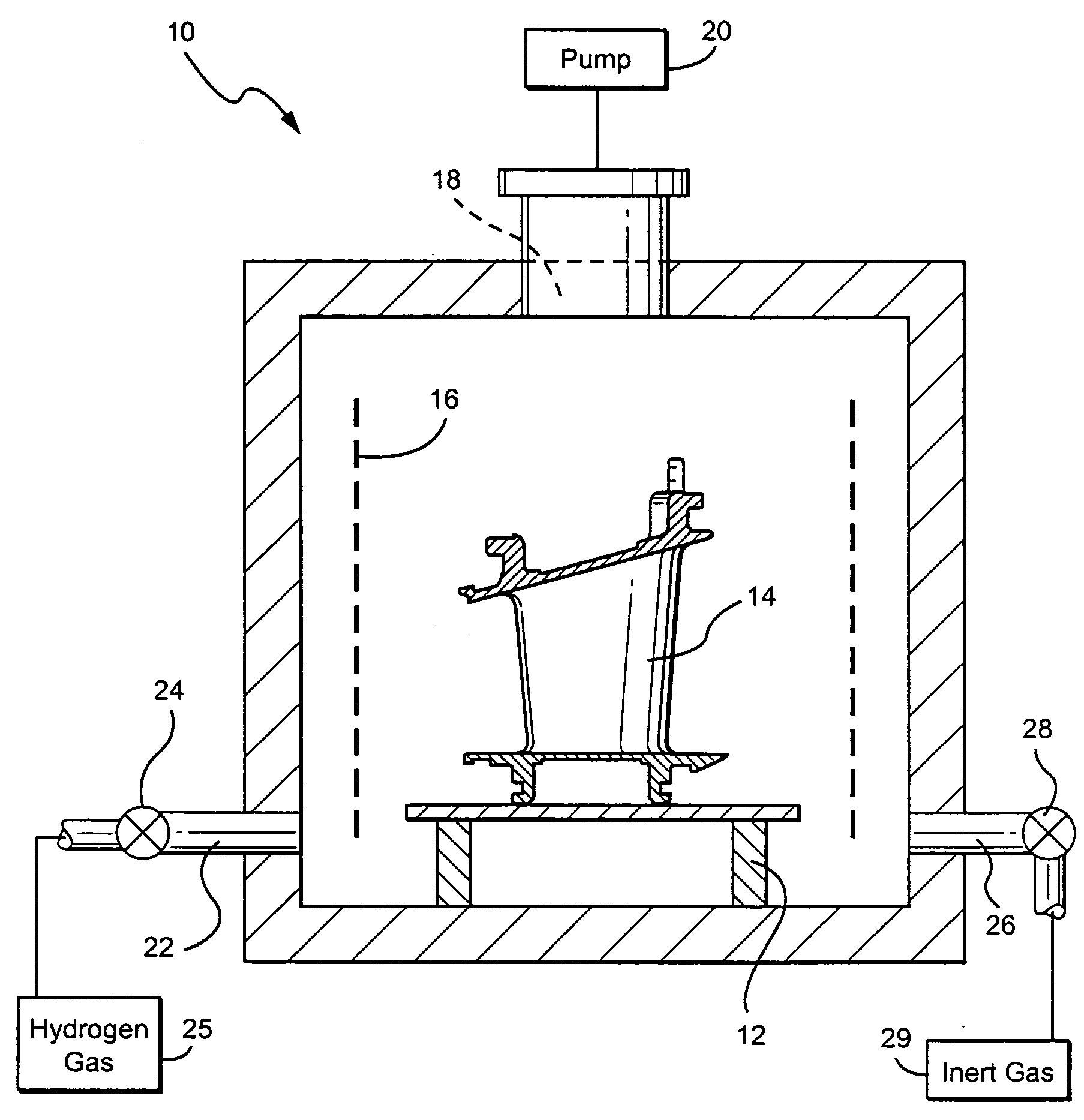
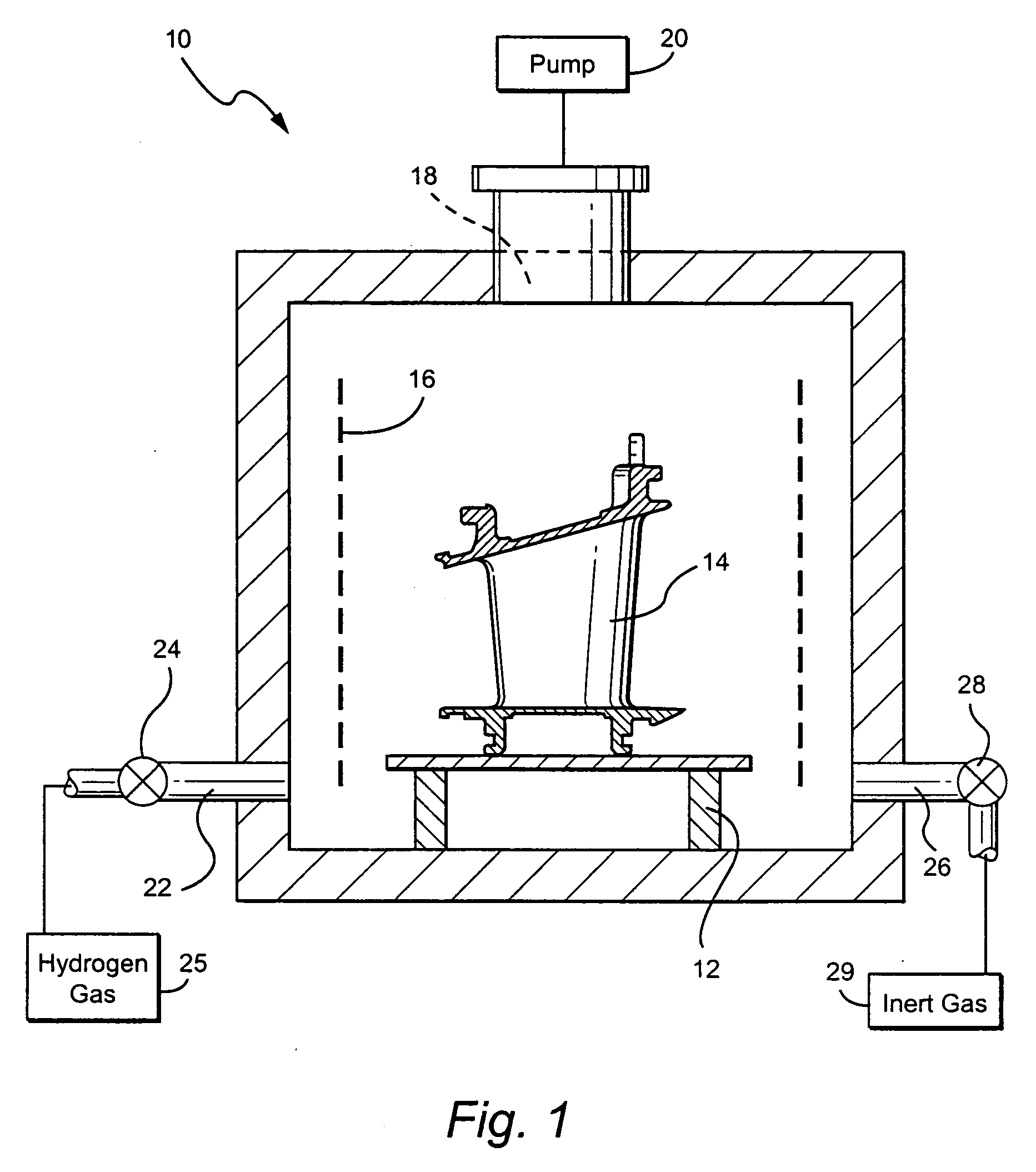
[0010] Referring to the drawing figures, there is illustrated a vacuum furnace, generally designated 10, including a support 12 for the article or component 14 which is to be cleaned. In this instance, a nozzle 14 for a gas turbine is illustrated on support 12. The component is formed of a metallic material and the cleaning process hereof is particularly applicable to components formed of a cobalt-based alloy, stainless steel or mild steel, such as nozzle 14. It will be appreciated that the component 14 to be cleaned has been in service and may have surface contaminants including oxides and / or surface cracks. Those surfaces require cleaning before a refurbishing process can go forward, e.g., before an ADH process can be employed to repair or refurbish the surfaces.

[0011] The vacuum furnace 10 includes a plurality of radiant heating elements 16 for radiantly heating the component(s), e.g., the nozzle 14 disposed within the vacuum furnace. The vacuum furnace 10 also includes an outle...


PUM

PropertyMeasurementUnit
temperatureaaaaaaaaaa
time periodaaaaaaaaaa
temperatureaaaaaaaaaa

Abstract

The pulsed partial pressure hydrogen cleaning of cobalt-based alloys in turbine components is achieved by disposing the component within a vacuum furnace and heating the component. Upon heating to about 1400° F., a partial pressure hydrogen gas and a vacuum are repetitively cycled within the furnace by supplying in each cycle a fresh supply of hydrogen gas, followed by removal of reaction products between the hydrogen gas and surface contaminants and substantially all residual hydrogen gas from within the furnace. The repetitious cycling renders the surfaces clean, enabling refurbishment thereof by activated diffusion healing repair.

Description

BACKGROUND OF THE INVENTION [0001] The present invention relates to methods for cleaning metallic surfaces using pulsed hydrogen in a vacuum furnace and particularly relates to methods for cleaning the surfaces of turbine components formed of metallic materials, particularly and for example, cobalt-based alloys, stainless steel and mild steels. [0002] Metallic components, for example, turbine components, particularly turbine nozzles formed of cobalt alloys, develop surface contaminants including surface oxides and surface cracks during usage over time and require refurbishing. Before being refurbished, however, the component surfaces must be cleaned to eliminate the contaminants, e.g., surface oxides including oxidation within the cracks which inhibits the repair of cracks and surface distress. Surface oxides in particular prevent the flow of a fresh material, e.g., a filler of activated diffusion healing (ADH) material, at elevated temperatures due to high surface tension. ADH is a...

Claims


Application Information

Patent Timeline
Patent Type & Authority Applications(United States)
IPC IPC(8): B08B7/00
CPCB08B7/0071
Inventor BUDINGER, DAVID EDWINGALLEY, RONALD LANCEPEZZUTTI, MARK DEAN
Owner GENERAL ELECTRIC CO
Why Eureka
Try Eureka