Directional casing and liner drilling with mud motor

a mud motor and casing technology, applied in the direction of directional drilling, borehole drives, drilling machines and methods, etc., can solve the problems of drilling string stuck in the borehole, other problems are often encountered, and the process is very time-consuming and costly

Inactive Publication Date: 2005-06-16
SCHLUMBERGER TECH CORP
View PDF43 Cites 42 Cited by
  • Summary
  • Abstract
  • Description
  • Claims
  • Application Information

AI Technical Summary

Benefits of technology

[0029] In one or more embodiment, the invention relates to a directional drilling system that includes a casing string, a mud motor operatively coupled to the casing string, a rotary steerable system operatively coupled to the mud motor, and

Problems solved by technology

This process is very time consuming and costly.
Additionally, other problems are often encountered when tripping the drill string.
For example, the drill string may get stuck in the borehole while it is being removed.
These problems requ

Method used


Image

  • Directional casing and liner drilling with mud motor
  • Directional casing and liner drilling with mud motor
  • Directional casing and liner drilling with mud motor

Examples


Embodiment Construction

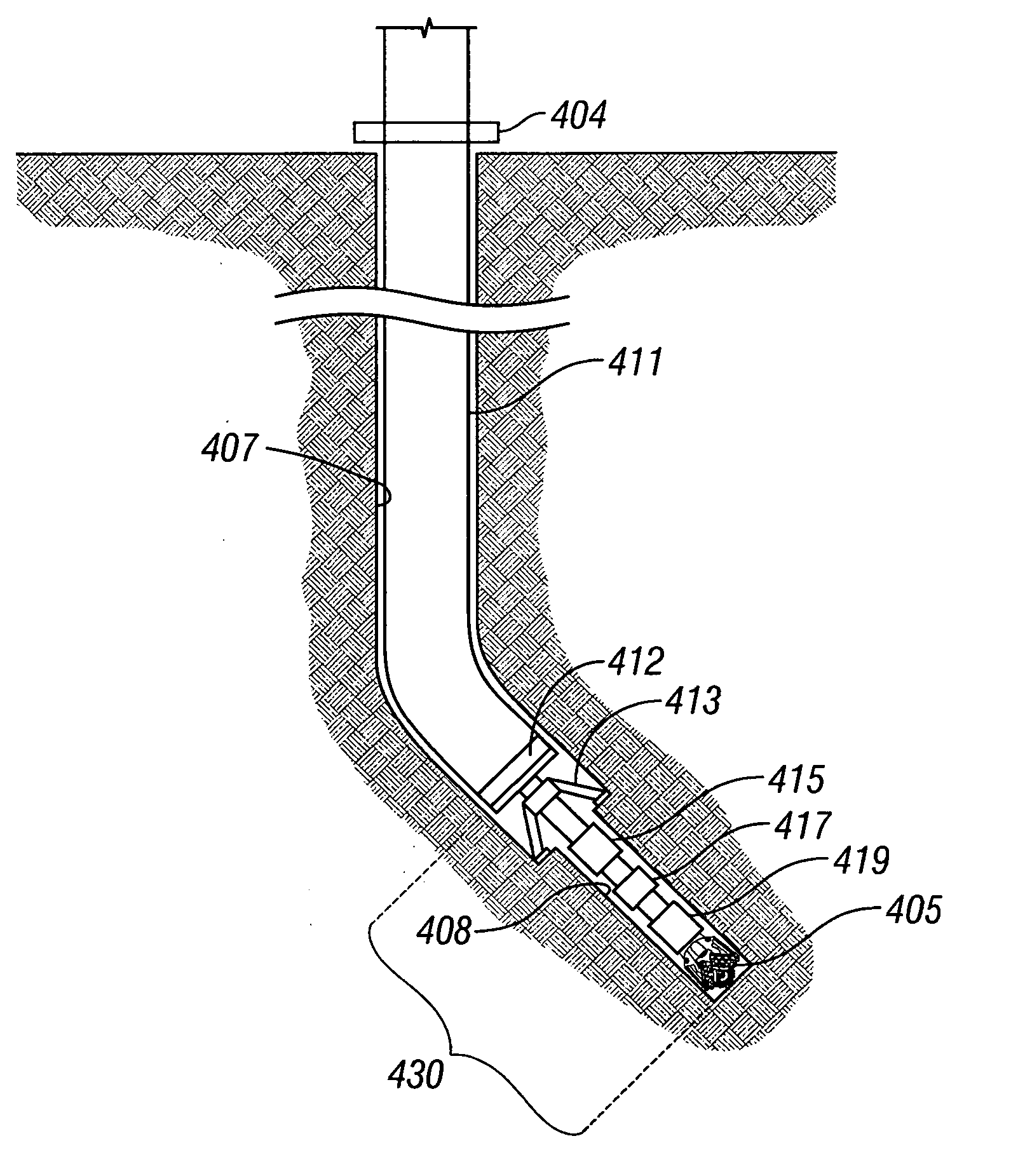
[0043] In some embodiments, the invention relates to a directional casing drilling system with a mud motor located near a rotary steerable system disposed inside the casing string. In other embodiments, the invention relates to a method of directional drilling with casing.

[0044]FIG. 4 shows a directional casing drilling system in accordance with one embodiment of the invention. A bottom hole assembly 430 (“BHA”) is positioned below a casing string 411 that is used as a drill string. It is noted that in some embodiments, some of the components of the BHA 430 may be positioned in a different order than is shown in FIG. 4 (as described below), and some components may be disposed inside the casing string 411. The exact position of each component of the BHA 430 is not intended to limit the invention.

[0045] The casing string 411 transmits rotary motion and downward force (called weight-on-bit or “WOB”) to a drill bit 405 positioned below the lower end of the casing string 411. The drill...


PUM


Abstract

A directional casing drilling system includes a casing string, a mud motor operatively coupled to the casing string, a rotary steerable system operatively coupled to the mud motor, and a drill bit operatively coupled to the rotary steerable system.

Description

BACKGROUND OF INVENTION [0001] Wells are generally drilled into the ground to recover natural deposits of hydrocarbons and other desirable materials trapped in geological formations in the Earth's crust. A well is typically drilled using a drill bit attached to the lower end of a “drill string.” The drill string is a long string of sections of drill pipe that are connected together end-to-end. Drilling fluid, called “mud,” is typically pumped down through the drill string to the drill bit. The drilling fluid lubricates and cools the drill bit, and it carries drill cuttings back to the surface in the annulus between the drill string and the borehole wall. [0002] In conventional drilling, a well is drilled to a selected depth, and then the wellbore is typically lined with a larger-diameter pipe, usually called “casing.” Casing typically consists of casing sections connected end-to-end, similar to the way drill pipe is connected. To accomplish this, the drill string and the drill bit a...

Claims


Application Information

Patent Timeline
IPC IPC(8): E21B7/04E21B7/06E21B7/20E21B10/26
CPCE21B7/067E21B10/26E21B7/208E21B7/068E21B10/66
Inventor MORIARTY, KEITH ALANJOHNSON, MICHAEL ROBERT
Owner SCHLUMBERGER TECH CORP
Why Eureka
Try Eureka