
Self-position estimating device for leg type movable robots

a robot and self-positioning technology, which is applied in the direction of navigation instruments, manufacturing tools, instruments, etc., can solve the problems of rotational slipping (spin) of the foot, deviation from a desired gait, and the vertical position of the robot tends to deviate from the desired gait, and achieves high precision

Active Publication Date: 2005-06-16
HONDA MOTOR CO LTD
View PDF4 Cites 69 Cited by
  • Summary
  • Abstract
  • Description
  • Claims
  • Application Information

AI Technical Summary

Benefits of technology

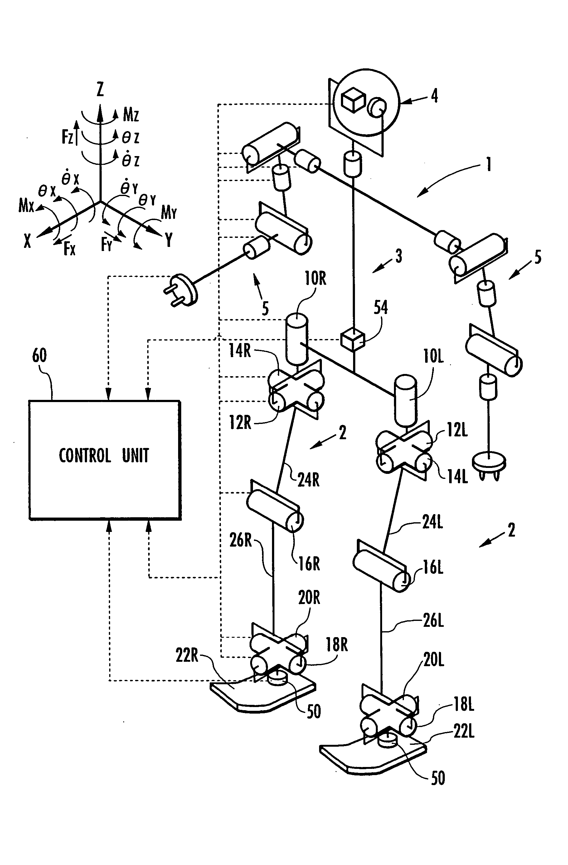
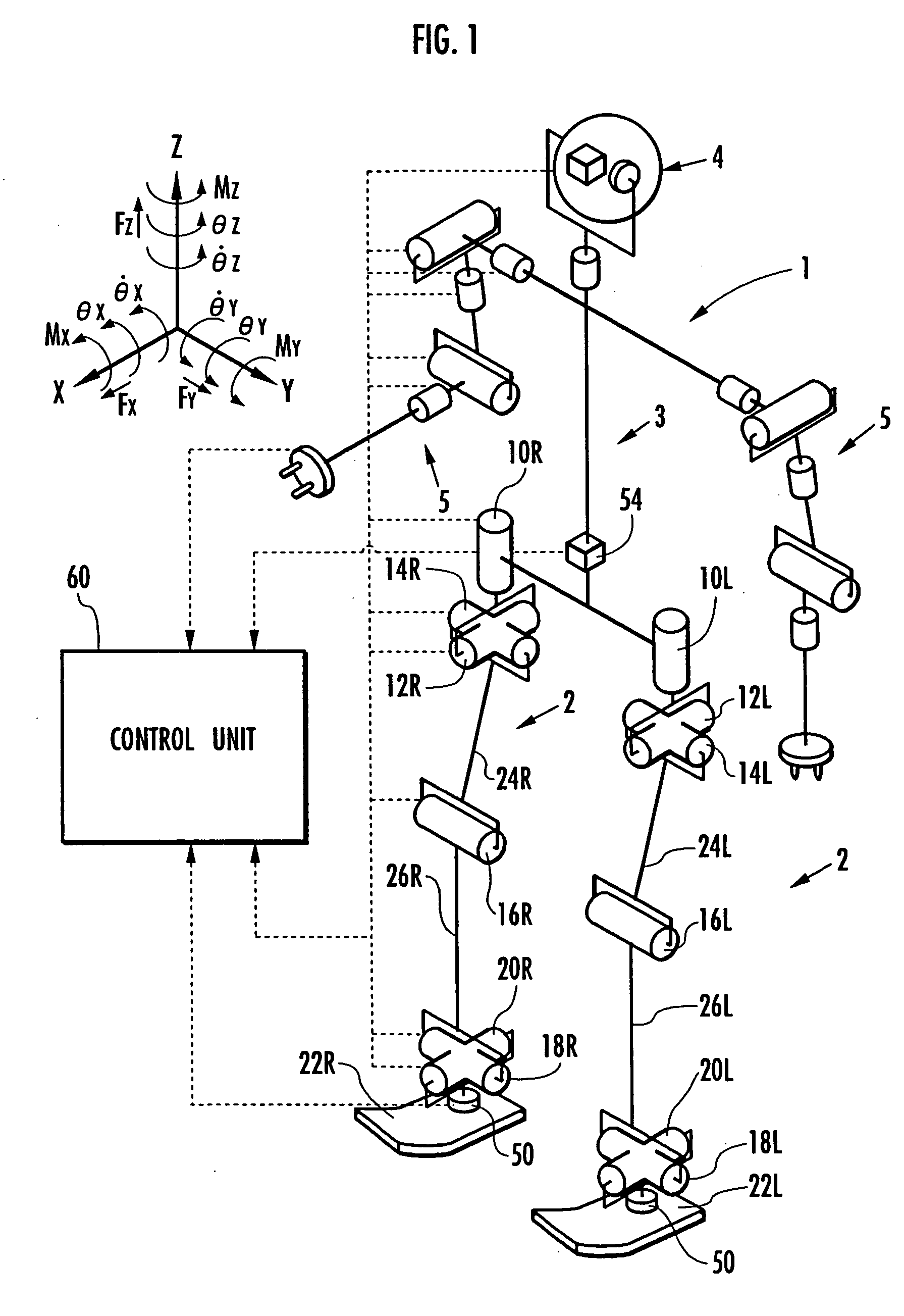
The present invention relates to a self-position estimating device for a leg type movable robot that can accurately determine its position in real-time. The device uses sensors to detect the actual position of the robot and calculates the deviation of the robot's posture from its desired position in the desired gait. By measuring and accounting for this deviation, the device can accurately track the robot's movement and position. This allows for precise control and estimation of the robot's self-position. The invention also takes into account the influence of rotational slipping or other factors that may occur during the robot's movement. The estimated position of the robot can be determined using a global coordinate system or a coordinate system determined in the vicinity of the robot's feet. Overall, the invention provides a more accurate and efficient means for controlling and positioning a leg type movable robot.

Problems solved by technology

Conventionally, a leg type movable robot has a problem that a reaction force caused by the moving robot swinging each leg overcomes the friction force between the foot (that is, the end portion of the leg) and the floor, causing a rotational slipping (spin) of the foot with respect to the floor, a rotation of the posture of the whole robot about the vertical axis and, thus, a deviation from a desired gait.
In addition, desired gaits to be generated are not always ones for straight walking with the body always kept in a vertical (upright) posture.
In addition, if the robot runs, the vertical position of the robot tends to deviate from the desired gait during a period in which all the legs float in the air (that is, a floating period).
However, the inertial navigation system estimates the position of the robot by integrating the detection value of the accelerometer two times, and thus, integration errors tend to accumulate to a significant extent.
However, it is difficult to keep the leg type movable robot at complete rest, because the joints have to constantly move slightly to stabilize the posture of the robot even when the robot,as a whole,is at rest in an upright posture.
Therefore, the inertial navigation calculation is started in a state where the initial values of the position and velocity are not 0, and thus, the estimation error tends to be significant.
However, it is difficult to achieve measurement of the height of a foot (that is, the end of a leg) of the robot from the floor with a precision on the order of millimeters or centimeters at a low cost, for example.

Method used


Image

  • Self-position estimating device for leg type movable robots
  • Self-position estimating device for leg type movable robots
  • Self-position estimating device for leg type movable robots

Examples


first embodiment

[0173] In the above description, the difference between the estimated body posture at the time when landing is ensured and the body posture of the desired gait is calculated as the posture rotational deviation's variation in step S2004. Strictly, however, it is preferable that the difference between the variation of the estimated body posture and the variation of the body posture of the desired gait for a period of one step is calculated as the posture rotational deviation's variation. However, in the first embodiment, since the algorithm described later is performed, the estimated body posture agrees with the body posture of the desired gait by itself at the start of one step. Therefore, the difference between the estimated body posture and the body posture of the desired gait equals to the difference between the variation of the estimated body posture and the variation of the body posture of the desired gait for a period of one step, and thus, either of them may be used.

[0174] The...

second embodiment

[0187] Also in the following, as for the second embodiment, the current estimated supporting leg coordinate system is preferably determined so as to the Z axis aligned with the vertical direction. As for the third and the following embodiments, a similar strategy may be used if the self position deviation due to spinning has to be primarily handled.

[0188] As described above, in the first embodiment, assuming that the actual behavior of the robot 1 is a rotation of the robot 1 and the estimated supporting leg coordinate system, the estimated supporting leg coordinate system being a local coordinate system that describes the movement of the robot 1, and the robot 1 moving following the desired gait in the estimated supporting leg coordinate system, about a predetermined posture rotation center determined by the posture rotation center determining means (in the processing in step S2006) by the posture rotational deviation's variation, which is a variation, during one step, of the diffe...

third embodiment

[0209]FIG. 14 is a flowchart showing a self-position estimating process in step S016 in FIG. 9 according to the

[0210] In the third embodiment, unlike the first and second embodiments, for each control cycle, the posture rotation (or spin) of the estimated supporting leg coordinate system is estimated, so that the estimated supporting leg coordinate system is updated. In addition, the body posture is estimated at instants during each control cycle, and the body position (strictly, the position of the representative point of the body) is estimated at instants during each control cycle.

[0211] Specifically, first, in step S2200, an estimated body posture is determined, as in the first embodiment.

[0212] Then, the process proceeds to step S2202, where the difference between the variation of the estimated body posture seen from the global coordinate system in the control cycle and the variation of the body posture of the desired gait seen from the global coordinate system in the control ...


PUM


Abstract

Based on a detected or estimated value of an actual posture of a predetermined part, such as a body 3, of a robot 1 and a deviation the actual posture from a posture of a desired gait, a posture rotational deviation's variation is determined as the temporal variation of the deviation, and the position of the robot 1 (for example, the position where the robot comes into contact with a floor) is estimated on the assumption that the robot 1 rotates about a rotation center by the rotational deviation's variation. In addition, in accordance with the difference between the estimated position and the estimated position of the robot 1 determined by an inertial navigation method using an accelerometer or the like, the estimated position of the robot 1 determined by the inertial navigation method is corrected, thereby improving the precision of the estimated position.

Description

TECHNICAL FIELD [0001] The present invention relates to a self-position estimating device for a leg type movable robot. BACKGROUND ART [0002] Conventionally, a leg type movable robot has a problem that a reaction force caused by the moving robot swinging each leg overcomes the friction force between the foot (that is, the end portion of the leg) and the floor, causing a rotational slipping (spin) of the foot with respect to the floor, a rotation of the posture of the whole robot about the vertical axis and, thus, a deviation from a desired gait. [0003] In addition, desired gaits to be generated are not always ones for straight walking with the body always kept in a vertical (upright) posture. A desired gait may involve a rotation or a forward, rearward, leftward or rightward inclination of the whole robot or the body thereof. That is, a desired gait may involve a posture rotation of the whole robot (or a posture rotation of a representative part, such as the body). Thus, in this spe...

Claims


Application Information

Patent Timeline
Patent Type & Authority Applications(United States)
IPC IPC(8): B25J13/08B62D57/02B62D57/032G01C19/00G01C21/16G01P15/18
CPCB25J13/088G01C21/16B62D57/032B62D57/02G01C21/185G01C21/188B25J5/00
Inventor TAKENAKA, TORUMATSUMOTO, TAKASHI
Owner HONDA MOTOR CO LTD
Learn More