
32V H-bridge driver with CMOS circuits

a technology of h-bridge driver and cmos circuit, which is applied in the direction of digital recording, synchronous motor starter, ac motor stopper, etc., can solve the problems of high technology cost, easy control of motors, and difficult safety and reliability, and achieve accurate and fast switching of said h-bridge driver

Inactive Publication Date: 2005-06-16
DIALOG SEMICONDUCTOR GMBH
View PDF8 Cites 13 Cited by
  • Summary
  • Abstract
  • Description
  • Claims
  • Application Information

AI Technical Summary

Benefits of technology

"The present invention is about a circuit for driving a DC-motor using CMOS technology. The circuit includes a control logic circuit and a power management module that work together to accurately and quickly switch the motor. The circuit also includes a charge pump and a means for reverse supply protection to ensure the motor operates safely and efficiently. The circuit is designed to be cost-effective and can be used to drive a 32-volt H-bridge. Overall, the invention provides a reliable and efficient solution for driving DC-motors using CMOS technology."

Problems solved by technology

However, making the motor easy to control, safe, and reliable isn't an easy task Most of the motors in today's vehicles conduct less than an average of 6 Ampere.
The challenge for the designer of such motor controller is to find a reliable, efficient and cost effective solution.
These technologies are expensive and it is desirable to find solutions that are less expensive.

Method used


Image

  • 32V H-bridge driver with CMOS circuits
  • 32V H-bridge driver with CMOS circuits
  • 32V H-bridge driver with CMOS circuits

Examples


Embodiment Construction

[0025] The preferred embodiments disclose a circuit of a cost-efficient motor bridge driver interface using a charge pump and a H-bridge. Said circuit provides has very fast and accurate switching capabilities and can perform up to at least 40 V maximum voltage as required for example by the automotive industry.

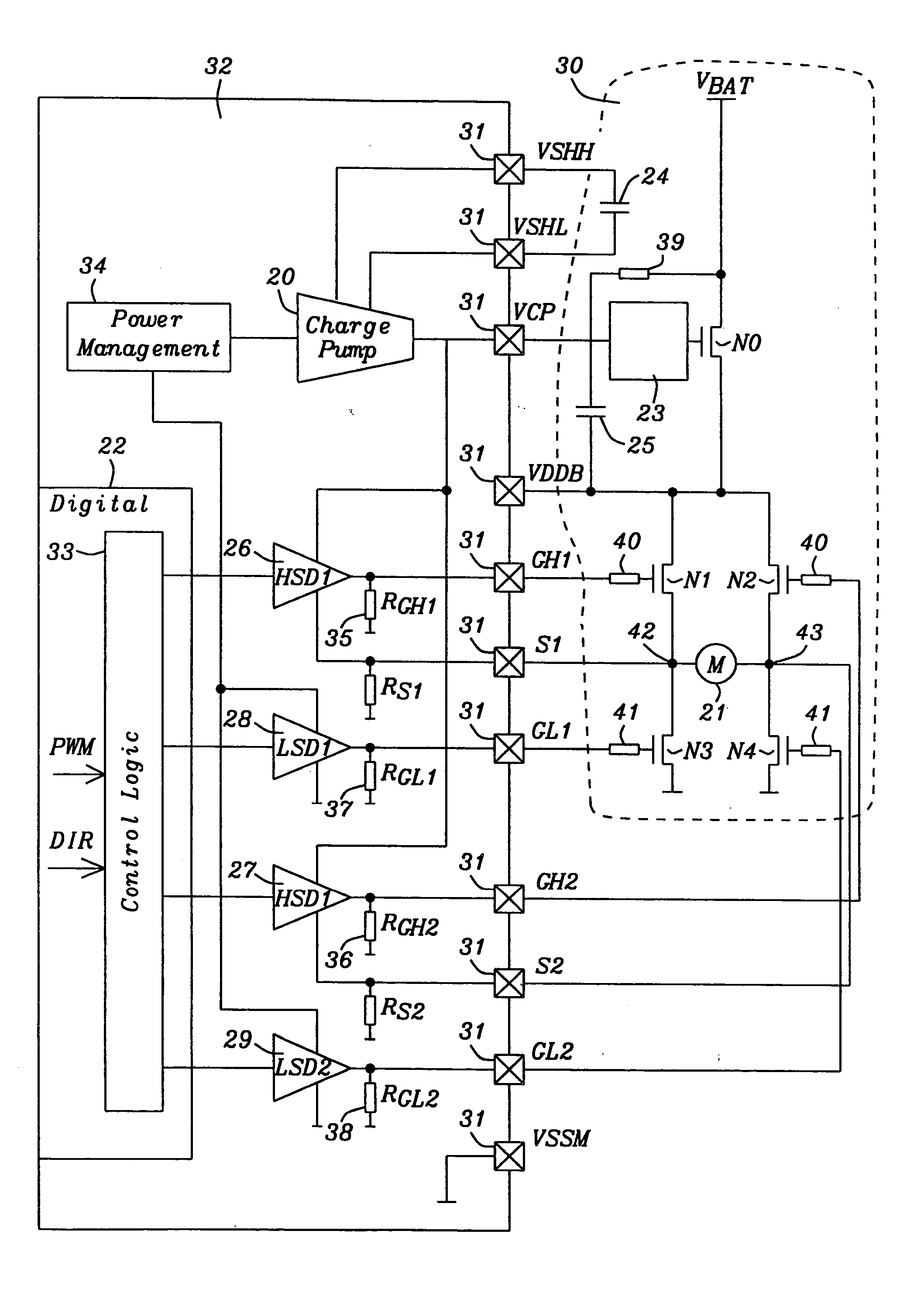
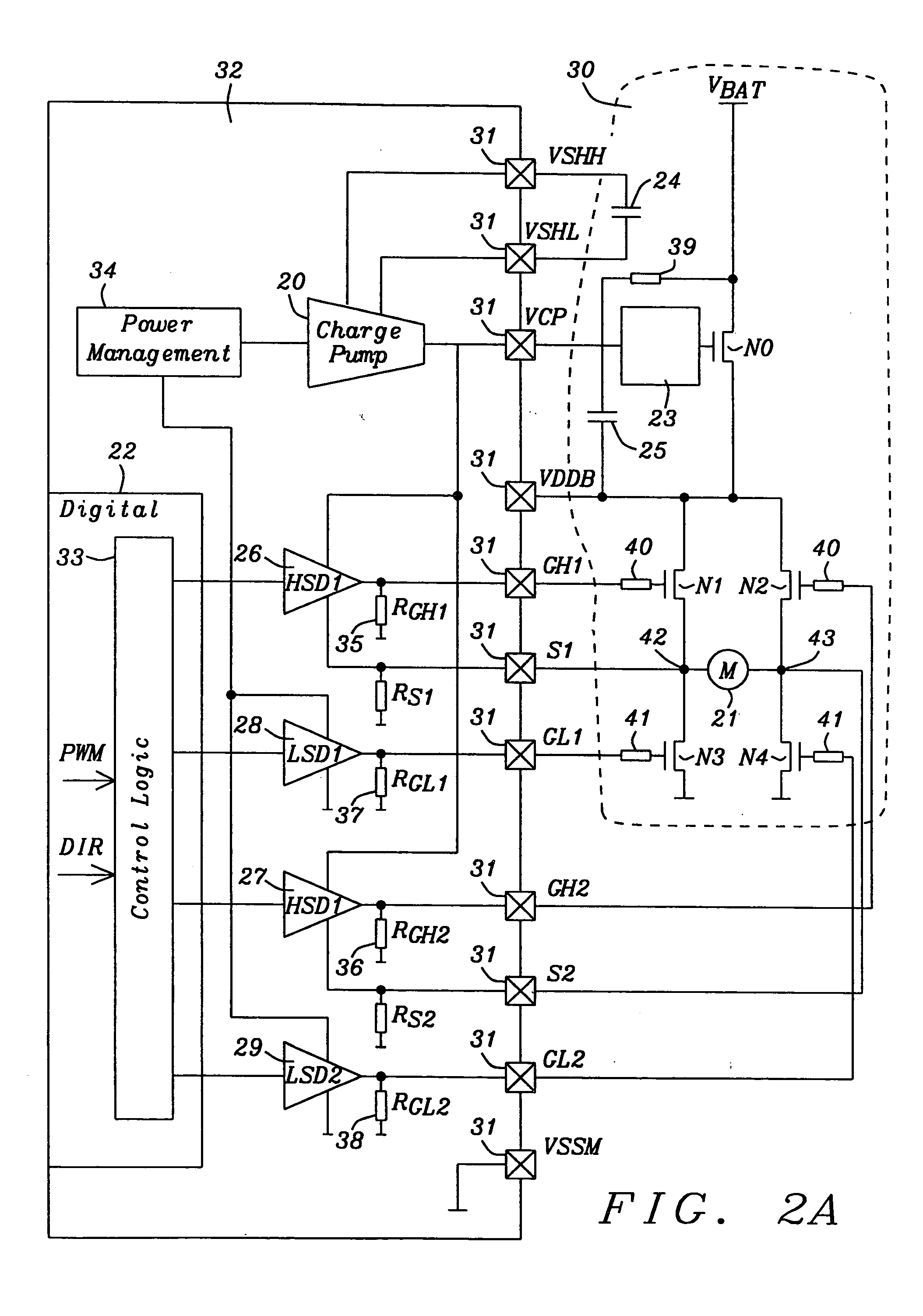
[0026]FIG. 2A shows a functional block diagram of a preferred embodiment of said motor bridge driver interface. Said motor bridge driver interface is designed to control four external N-channel MOS power transistors N1, N2, N3, and N4 in a H-bridge configuration for DC-motor 21 driving. The interface, being implemented on an ASIC 32, is comprising a charge pump 20, having two external capacitors 24 and 25, two high-side drivers (HSD126 and HSD227) and two low-side drivers (LSD128 and LSD229) circuits, two voltage dividers 35 and 36 located at the output of said high-voltage drivers, being connected to the mid-points 42 respective 43 of said H-bridge and to ground, providing ...


PUM


Abstract

A motor bridge driver interface, implemented in an ASIC using cost-efficient CMOS technology, is designed to control four external MOS power transistors in a H-bridge configuration for DC-motor driving to achieve accurate and fast switching. Said driver interface is comprising a charge pump for generating the control voltage for the high-side N-channel MOS transistors, high-side (HSD) circuits, low-side (LSD) circuits and a complex digital interface for supplying the control signals in a programmable timing scheme. A “strong” charge pump is used to realize a simple CMOS switch to steer the output to the high-side transistors of said H-bridge. The motor bridge is connected to the battery supply by an additional N-channel MOS transistor to implement a reverse supply protection.

Description

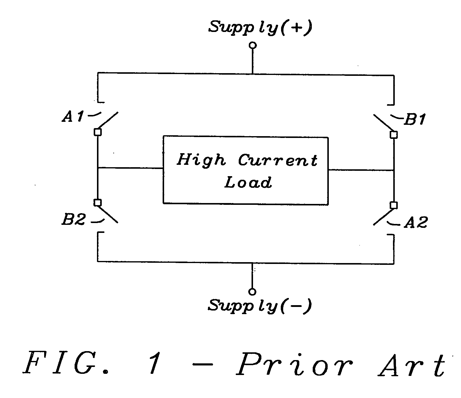
BACKGROUND OF THE INVENTION [0001] (1) Field of the Invention [0002] The present invention relates to integrated circuits for a motor bridge interface, and particularly to control four external N-channel MOS power transistors in a H-bridge configuration for DC-motor driving. [0003] (2) Description of the Prior Art [0004] Motors play a key role in the increasing comfort and convenience in today's vehicles, providing functions from adjusting seats or headlamps to lifting windows and moving sunroof doors. However, making the motor easy to control, safe, and reliable isn't an easy task Most of the motors in today's vehicles conduct less than an average of 6 Ampere. [0005] Motors normally need to be operated in both forward and reverse. This requirement leads to a circuit layout known as an H-bridge. FIG. 1 prior art shows a simple conceptual schematic of an H-bridge. A basic H-bridge has four switches, relays, transistors, or other means of completing a circuit to drive a motor. In FIG....

Claims


Application Information

Patent Timeline
Patent Type & Authority Applications(United States)
IPC IPC(8): H02H11/00H03K17/06H03K17/687
CPCH02H11/003H03K17/6871H03K17/063
Inventor KERNHOF, JURGENMARSCHALKOWSKI, ERIC
Owner DIALOG SEMICONDUCTOR GMBH
Learn More