
Method and apparatus for multiple battery cell management

a battery cell and management method technology, applied in the field of multiple battery systems, can solve the problems of large mechanical relays, large bmss, and overcharged lithium batteries, and achieve the effect of efficient and safe battery cell charge management and more efficient bms scaling

Inactive Publication Date: 2005-06-16
LG CHEM LTD
View PDF10 Cites 75 Cited by
  • Summary
  • Abstract
  • Description
  • Claims
  • Application Information

AI Technical Summary

Benefits of technology

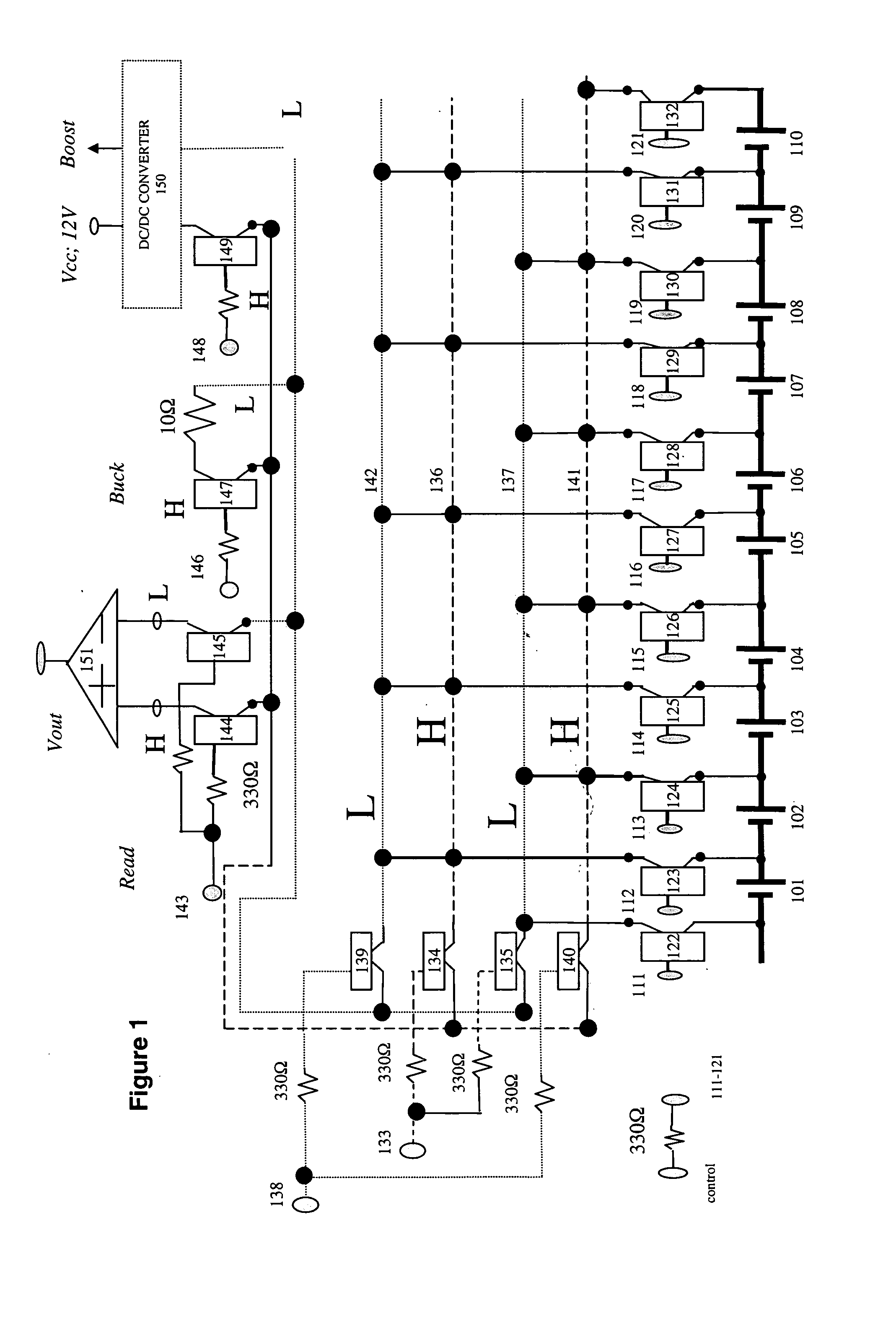
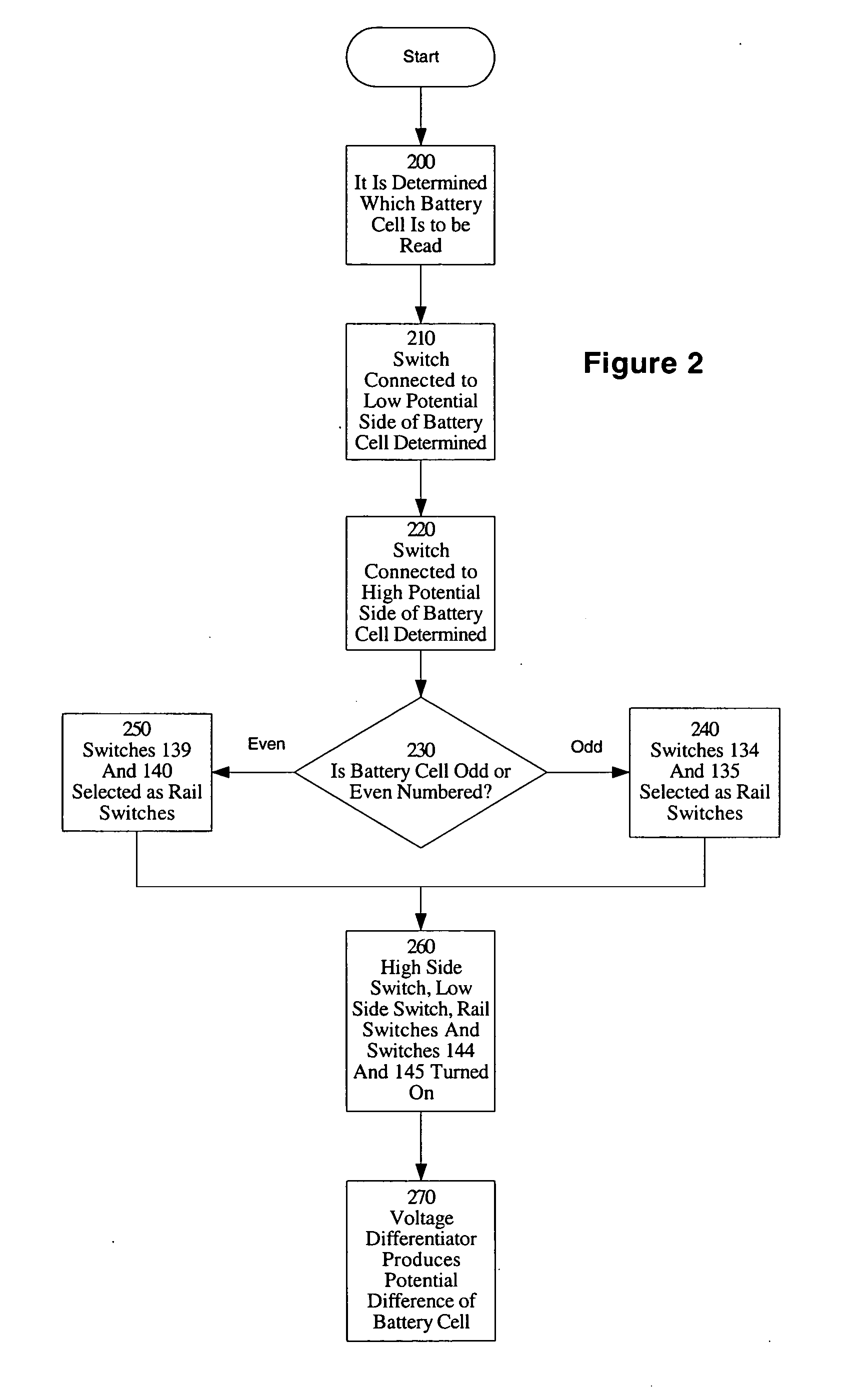
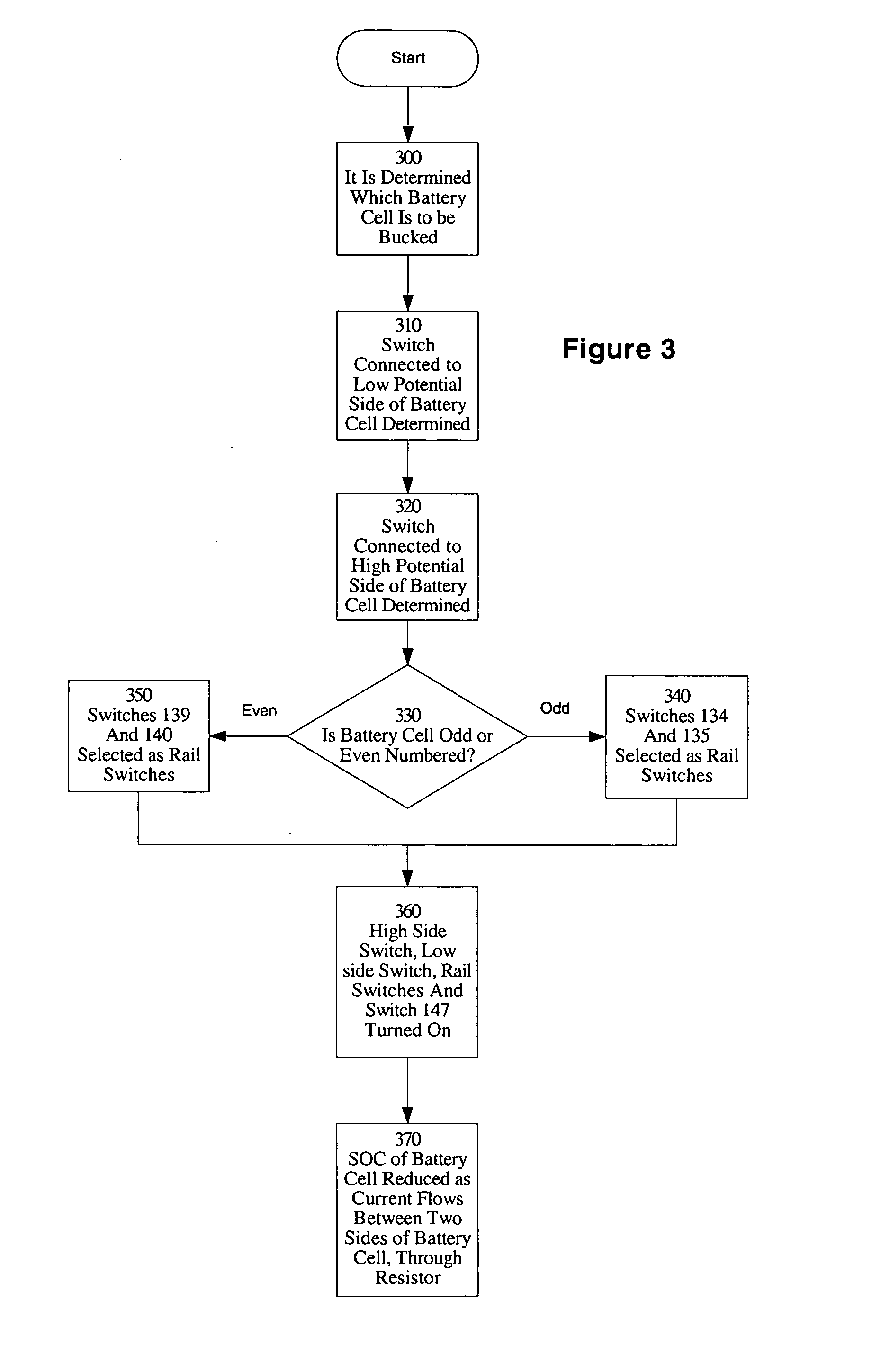
[0008] Embodiments of the present invention are directed to a method and apparatus for multiple battery cell management. In one embodiment of the present invention, a solid state relay (SSR) is used instead of a mechanical relay in a BMS. The SSR is smaller and faster than a mechanical relay, enabling smaller BMSs that more efficiently and safely manage battery cell charge. In another embodiment, a plurality of battery cells are connected to two rails, using four SSRs to control access to the battery cells.
[0009] In one embodiment, a plurality of battery cells are grouped together and controlled as one module of a multi-module BMS. In one embodiment, each module has 10 battery cells in series. In other embodiments, other numbers and arrangements of batteries are used. The modular design enables more efficient scaling of the BMS. In one embodiment, the BMS controls 4 modules. In other embodiments, the BMS controls other numbers of modules. In one embodiment, each module is controlled by control signals passing through logical gates. In another embodiment, each module is controlled by control signals passing through a programmed circuit (e.g., an EPROM or Programmed Logic Array).

Problems solved by technology

However, LiPb batteries may ignite if overcharged.
However, mechanical relays are relatively large and slow.
Thus, BMSs are larger than desired, and may not be able to respond quickly enough to ensure safe and efficient operation of multiple battery cell systems.

Method used


Image

  • Method and apparatus for multiple battery cell management
  • Method and apparatus for multiple battery cell management
  • Method and apparatus for multiple battery cell management

Examples


Embodiment Construction

[0018] The invention is a method and apparatus for multiple battery cell management. In the following description, numerous specific details are set forth to provide a more thorough description of embodiments of the invention. It is apparent, however, to one skilled in the art, that the invention may be practiced without these specific details. In other instances, well known features have not been described in detail so as not to obscure the invention.

[0019] Solid State Relays

[0020] In one embodiment of the present invention, a solid state relay (SSR) is used instead of a mechanical relay in a BMS. The SSR is smaller and faster than a mechanical relay, enabling smaller BMSs that more efficiently and safely manage battery cell charge. In one embodiment, the solid state relay is an optically isolated field-effect transistor (FET). In one embodiment, the input level for controlling the SSR is matched to the voltage level of the control circuit (e.g., 5V and 0V). In one embodiment, th...


PUM


Abstract

Embodiments of the present invention are directed to a method and apparatus for multiple battery cell management. In one embodiment, a solid state relay is used instead of a mechanical relay in a BMS. The SSR is smaller and faster than a mechanical relay, enabling smaller BMSs that more efficiently and safely manage battery cell charge. In another embodiment, a plurality of battery cells are connected to two rails, using four SSRs to control access to the battery cells. In one embodiment, a plurality of battery cells are grouped together and controlled as one module of a multi-module BMS. In one embodiment, each module has 10 battery cells in series. In one embodiment, the BMS controls 4 modules. In one embodiment, each module is controlled by control signals passing through logical gates. In another embodiment, each module is controlled by control signals passing through a programmed circuit.

Description

BACKGROUND OF THE INVENTION [0001] 1. Field of the Invention [0002] The present invention relates to the field of multiple battery systems, and in particular to a method and apparatus for multiple battery cell management. [0003] 2. Background Art [0004] Recently, several types of batteries have been developed for electrical, hybrid electrical vehicles, and launch assistant 42V battery applications. LiPb has a higher energy density than other batteries developed so far, but it has stringent management requirements for safety and extension of battery life. Balancing the cells, estimating the state of charge (SOC), and controlling temperature require a very sophisticated Battery Management System (BMS). This problem can be better understood with a review of multiple battery systems. [0005] Multiple Battery Systems [0006] Some systems connect a plurality of battery cells in series. Typically, the cells in series are charged collectively rather than individually. However, LiPb batteries ...

Claims


Application Information

Patent Timeline
IPC IPC(8): H02J7/00
CPCY02T10/7055H02J7/0019Y02T10/70
Inventor LIM, MYOUNGHOFLAHERTY, MARK J.YI, WOO-CHULGRIFFIN, KEITH
Owner LG CHEM LTD
Learn More