Intelligent Cooling System for Traction Transformer of EMU

A traction transformer and cooling system technology, applied in transformer/inductor cooling, non-electric variable control, control/regulation systems, etc., can solve the problem of inability to accurately control the heat transfer process of traction transformers, low energy utilization efficiency, and cooling intensity adjustment. In order to improve energy utilization efficiency, reduce auxiliary power consumption, and meet the effect of energy saving

Active Publication Date: 2018-09-11
CRRC DALIAN INST CO LTD
View PDF9 Cites 0 Cited by
  • Summary
  • Abstract
  • Description
  • Claims
  • Application Information

AI Technical Summary

Problems solved by technology

In the prior art, the cooling system adopted by the heat source in the under-vehicle equipment compartment of the electric train set has the disadvantages of constant cooling intensity adjustment and low energy utilization efficiency; some cooling systems used in electric train sets such as traction transformer cooling systems, Traction transformer cooling system, traction motor cooling system, etc. are still passive cooling systems. The heat dissipation design standard of these cooling systems is to meet the heat dissipation requirements at full load. The control strategy is an extensive single-point control method. Take the traction transformer cooling system as an example. , the general control strategy in the prior art is: the fan used in the cooling system has two speed operation modes: high speed and low speed. When the top layer oil temperature reaches T1+10°C, the fan adopts a low-speed operation mode; this control mode cannot accurately control the oil flow of the traction transformer and the cooling air flow according to the operating environment and operating conditions of the electric multiple units. flow, and thus cannot accurately control the heat transfer process of the heat source in the traction transformer, resulting in excessive cooling in low temperature environment or partial load conditions, high auxiliary power, resulting in energy waste, poor economy, and high noise

Method used


Image

  • Intelligent Cooling System for Traction Transformer of EMU
  • Intelligent Cooling System for Traction Transformer of EMU

Examples


Embodiment Construction

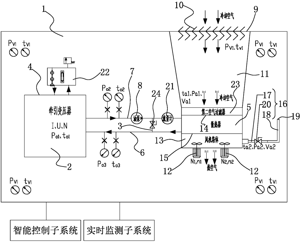
[0049] like figure 1 and figure 2 Shown is an intelligent cooling system for the traction transformer of an electric multiple train set, the electric multiple train set has an equipment cabin 1, the traction transformer 2 is arranged in the equipment cabin 1, and the included heat source components are placed in the oil tank 4, the The cooling system includes: a cooling device arranged in the equipment compartment 1; the cooling oil flowing out of the oil tank 4 takes away the heat generated by the heat source components; the cooling device includes: circulating with the oil tank 4 through the cooling oil The radiator 5 connected by the pipeline; the cooling oil circulation pipeline includes the oil inlet pipeline 6 and the oil outlet pipeline 7; the oil pump 8 installed on the oil outlet pipeline 7; the cooling oil flowing out from the oil tank 4 passes through the outlet The oil pipeline 7 and the oil pump 8 enter the radiator 5; the radiator 5 transfers heat from the cool...


PUM


Abstract

The invention discloses an intelligent cooling system for a traction transformer of an electric multiple unit. The electric multiple unit is provided with an equipment compartment, wherein the traction transformer is arranged in the equipment compartment, the traction transformer comprises a heat source part placed in an oil box, the cooling system comprises a cooling device arranged in the equipment compartment, heat generated by the heat source part is taken away by cooling oil flowing out of the oil box, the cooling device comprises a heat sink and an oil pump, the heat sink communicates with the oil box through a cooling oil circulation pipeline, the cooling oil circulation pipeline comprises an oil inlet pipeline and an oil outlet pipeline, the oil pump is arranged on the oil outlet pipeline, the cooling oil flowing out of the oil box passes through the oil outlet pipeline and the oil pump and enters the heat sink, the heat sink is used for transferring the heat to cooling air from the cooling oil, and the cooling oil passes through the oil inlet pipeline and returns to the oil box after the heat is released. By the intelligent cooling system, the cooling intensity can be automatically adjusted, and the energy utilization efficiency is improved.

Description

technical field [0001] The invention relates to the technical field of heat exchange, in particular to an intelligent cooling system for traction transformers of electric multiple train units. Background technique [0002] At present, the intelligent cooling technology applied to electric multiple units has not been fully understood and paid enough attention to. In the prior art, the cooling system adopted by the heat source in the equipment cabin under the electric train set has the disadvantages of constant cooling intensity adjustment and low energy utilization efficiency; some cooling systems used in electric train sets such as traction transformer cooling system, Traction transformer cooling system, traction motor cooling system, etc. are still passive cooling systems. The heat dissipation design standard of these cooling systems is to meet the heat dissipation requirements at full load, and their control strategy is an extensive single-point control method. Take the tr...

Claims


Application Information

Patent Timeline
Patent Type & Authority Patents(China)
IPC IPC(8): H01F27/12G01D21/02G05D23/20
CPCG01D21/02G05D23/20H01F27/12
Inventor 孔丽君刘俊杰李杨赵志强
Owner CRRC DALIAN INST CO LTD
Why Eureka
Try Eureka