Haptic feedback device with button forces

a haptic feedback and button technology, applied in the field of haptic feedback devices with button forces, can solve the problems of limited haptic feedback provided to the operator concerning the interactions of the slave with its environment, the type of master requires considerable operator training, and the control of the slave is not intuitive, etc., to achieve detailed and accurate control, easy operation, and easy control of objects

Inactive Publication Date: 2005-06-16
IMMERSION CORPORATION
View PDF99 Cites 143 Cited by
  • Summary
  • Abstract
  • Description
  • Claims
  • Application Information

AI Technical Summary

Benefits of technology

[0018] The improvements of the present invention provide a more natural haptic feedback interface device that is intuitive and easy to operate. The pincher mechanism of the present invention allows a user to easily control objects such as a gripper or virtual hand, and provides haptic feedback based on interactions of the controlled object to allow more detailed and accurate control. The moveable portion of the housing of the present invention provides another channel through which the user can experience haptic feedback independently of any other control mechanisms such as the pincher mechanism, allowing the user to experience feedback concerning interactions of the controlled object to a greater extent, which allows even further natural and accurate control of the object.

Problems solved by technology

One problem with joystick master controllers is that the control of the slave is not very intuitive, and achieving proficiency with this type of master requires considerable operator training.
One problem with haptic feedback used in master end effectors of the prior art is that the haptic feedback provided to the operator concerning the interactions of the slave with its environment is very limited and / or not well correlated to fine control of the slave, so that the operator receives only a crude sense of what is happening in the slave environment.
Furthermore, for slave devices having a jaw gripper, there is no haptic feedback provided to the operator concerning the movement and interaction of the jaw gripper with other objects.
In addition, current equipment for teleoperation can be expensive and often has reliability and stability problems in harsh environments such as underwater oil rig maintenance.
Another problem is the degree of control provided to the operator over the slave device.
Master control over such slave instruments as a gripper is often crudely performed with devices such as buttons and triggers, which do not greatly help the operator manipulate the gripper to perform highly delicate operations, and do not provide an intuitive control mechanism.
A problem with current haptic feedback devices, however, is that the haptic feedback is not very well integrated into some types of controllers, such as gamepads or other controllers besides traditional joysticks.

Method used


Image

  • Haptic feedback device with button forces
  • Haptic feedback device with button forces
  • Haptic feedback device with button forces

Examples


embodiment 120

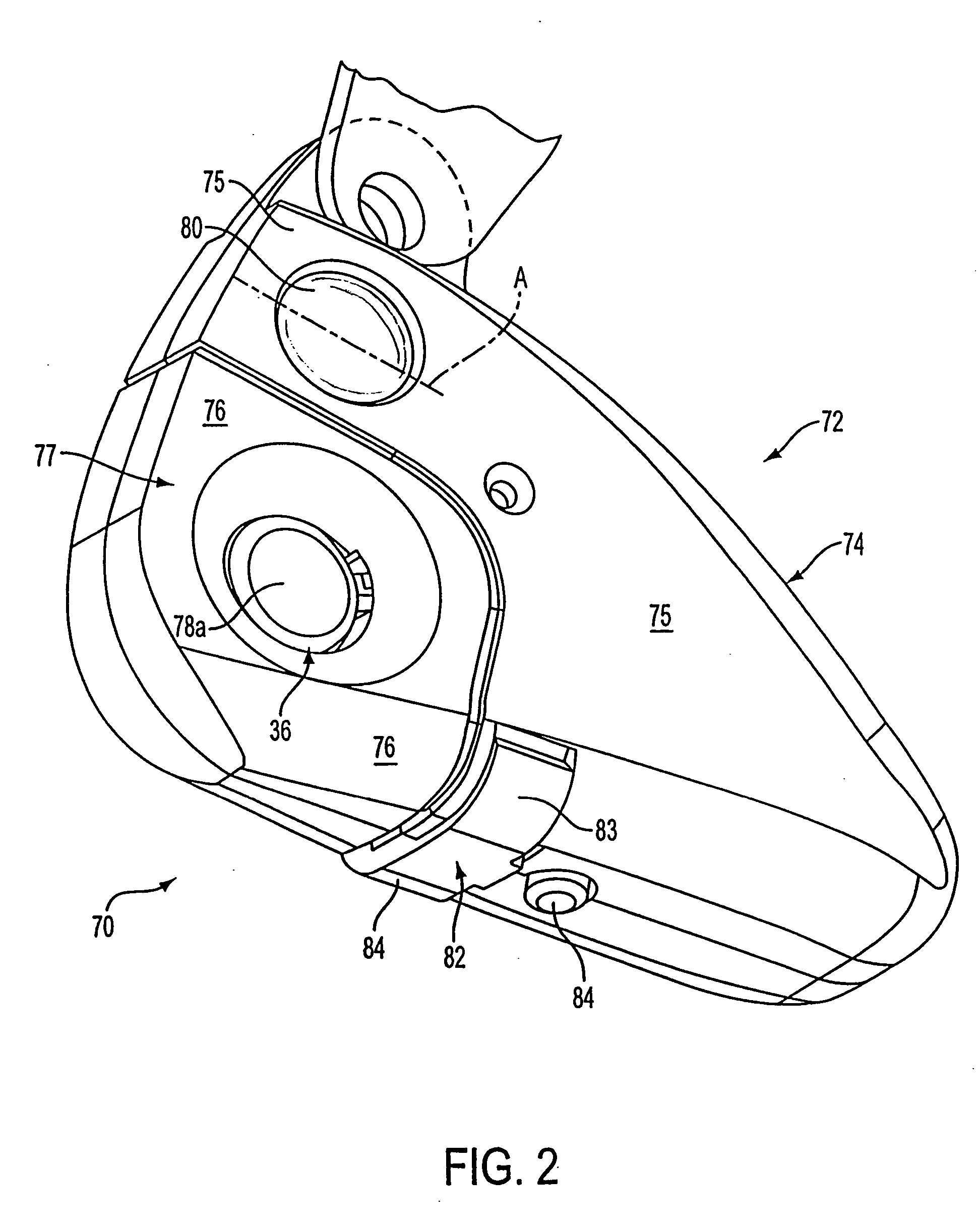
[0060]FIG. 4 is a perspective view of a second, preferred embodiment 120 of the controller 70 of FIG. 2, including both the moveable portion 76 of the housing and the force feedback gripper control 36. A portion of the housing 74 is removed to show the mechanism within controller 70.

[0061] The mechanism for moving the moveable portion 76 of the housing is substantially the same as described with reference to FIG. 3. The moveable portion 76 is moveably coupled to the fixed portion 75 of housing 74 by leaf springs 98 and 92, which are provided at a 90-degree relation to each other for support of the moveable portion. Actuator 102 outputs forces on leaf spring member 98, which moves moveable portion 76 relative to fixed portion 75. In addition, this causes movement of moveable portion 76 relative to the gripper mechanism 36, including finger pads 78 and gripper members 130. As in the embodiment of FIG. 3, an oscillating force is preferably output to cause a vibration of moveable portio...

embodiment 180

[0074]FIG. 7 is a perspective view of a different embodiment 180 of the controller 70 of FIG. 2, in which the entire controller 70 is used as a vibrotactile device or “shaker.” Controller 180 includes a roller 80 and buttons 82 and 84, as described above. Moveable portion 76 and leaf springs 98 and 92 can also be included, although they are not utilized for any particular function separate from the rest of housing 74, so that the moveable portion 76 can be made unitary with the housing 74 if desired.

[0075] Actuator 182 is included to provide vibrotactile feedback to the housing 74. One portion 184 of actuator 182 is grounded to housing 74, and a second portion or bobbin 186 moves with respect to the grounded portion 184. For example, a voice coil actuator similar to the actuator 150 described with reference to FIG. 6 can be used. In the described embodiment, the bobbin 186 is coupled to two leaf springs 188 and 190, and the leaf springs are in turn coupled to the housing 74. In oper...

embodiment 150

[0080]FIG. 9a is schematic diagram of the linkage mechanism 204 and actuator of the gripper control 200 of FIG. 8. The linkage mechanism of FIG. 9a amplifies motion of the gripper pads relative to actuator 124. A force F.sub.A is applied by the user when pushing down on the gripper portions 202a and 202b. For explanatory purposes, only one of the gripper pads 202 and gripper members 216 is shown in FIG. 9a. Gripper member 216 is coupled to a gripper portion 202 and is a lever arm that pivots about a coupling 215. The gripper member 216 is also rotatably coupled to a member 218 at the coupling 215, and the member 218 is rotatably coupled to a grounded member 220. Gripper member 216 is coupled to a linear-moving member 222 at a location on member 216 spaced from coupling 215. Member 222 is coupled to a moving portion of an actuator 226 which moves in a linear degree of freedom. A non-moving portion of the actuator 226 is grounded. For example, the actuator embodiment 150 of FIG. 6 can...


PUM


Abstract

A haptic feedback control device, such as a handheld remote control or handheld game controller, for controlling a graphical object within a graphical display and for outputting forces to a user. A housing includes a button, wherein the user engages the button with a finger. The button is depressible along a degree of freedom by the user. An actuator applies forces to the user through the button along the degree of freedom. A sensor detects displacement of the button along the degree of freedom when the button is depressed by the user. A process, local to the device, controls the actuator to generate the forces upon the button in the degree of freedom to provide a tactile sensation to the user contacting the button.

Description

CROSS REFERENCE TO RELATED APPLICATIONS [0001] This is a continuation application of U.S. application Ser. No. 09 / 741,310, filed Dec. 19, 2000, which is a continuation of U.S. application Ser. No. 09 / 156,802, filed Sep. 17, 1998, now U.S. Pat. No. 6,184,868. Each of which are incorporated herein by reference in their entirety.[0002] Certain inventions provided herein were made with government support under Contract Number N00014-98-C-0220, awarded by the Office of Naval Research. The government has certain rights in these inventions.BACKGROUND OF THE INVENTION [0003] The present invention relates generally to the interfacing with computer and mechanical devices by a user, and more particularly to devices used to interface with computer systems and telemanipulator devices and which provide haptic feedback to the user. [0004] Humans interface with electronic and mechanical devices in a variety of applications, and the need for a more natural, easy-to-use, and informative interface is ...

Claims


Application Information

Patent Timeline
Patent Type & Authority Applications(United States)
IPC IPC(8): A63F13/06G06F3/00G06F3/01G06F3/033
CPCA63F13/06A63F2300/1037A63F2300/1062A63F2300/8017G06F3/011G06F3/016G06F2203/015G06F3/03543G06F3/03545G06F3/0362G06F2203/013G06F2203/014G06F3/0338A63F2300/1006A63F2300/1087A63F2300/1056A63F13/285A63F13/218A63F13/23A63F13/92A63F2300/204A63F2300/1025A63F13/235A63F2300/1043A63F13/428A63F13/24A63F2300/1031A63F13/213A63F13/245
Inventor SHAHOIAN, ERIK J.HASSER, CHRISTOPHER J.ROSENBERG, LOUIS B.
Owner IMMERSION CORPORATION
Why Eureka
Try Eureka