Heat-radiating structure of electronic apparatus

a technology of electronic equipment and heat-radiating structure, which is applied in the direction of electrical apparatus casings/cabinets/drawers, instruments, and semi-conductor/solid-state device details, etc., can solve the problem of overfilling of thermal conductive components, and achieve the effect of improving heat-radiating performance and variable siz

Active Publication Date: 2005-06-16
PANASONIC CORP
View PDF5 Cites 13 Cited by
  • Summary
  • Abstract
  • Description
  • Claims
  • Application Information

AI Technical Summary

Benefits of technology

[0011] Therefore, an object of the present invention is to provide a heat-radiating mechanism and a heat-radiating structure that accommodates a variation in the size due to a component tolerance when conducting and radiating heat of a heat-generating component in an electronic apparatus to the outside and has improved heat-radiating performance.
[0014] In the heat-radiating mechanism of an electronic apparatus of the present invention, a graphite sheet is pressed elastically against a heat-generating component such as CPU and a heat-radiating component such as a keyboard supporting plate on the back of a keyboard, utilizing the flexibility of the graphite sheet, so that a clearance generated therebetween can be minimized. As a result, the contact thermal resistance between the heat-generating component and the graphite sheet and between the graphite sheet and the keyboard supporting plate is reduced, and thus the heat-radiating performance of the electronic apparatus can be improved.

Problems solved by technology

However, the flexible thermal conductive member is filled in a little excessive amount to accommodate a change in the thermal resistance space size Vis of the thermal conduction resistance space IS.

Method used


Image

  • Heat-radiating structure of electronic apparatus
  • Heat-radiating structure of electronic apparatus
  • Heat-radiating structure of electronic apparatus

Examples


first embodiment

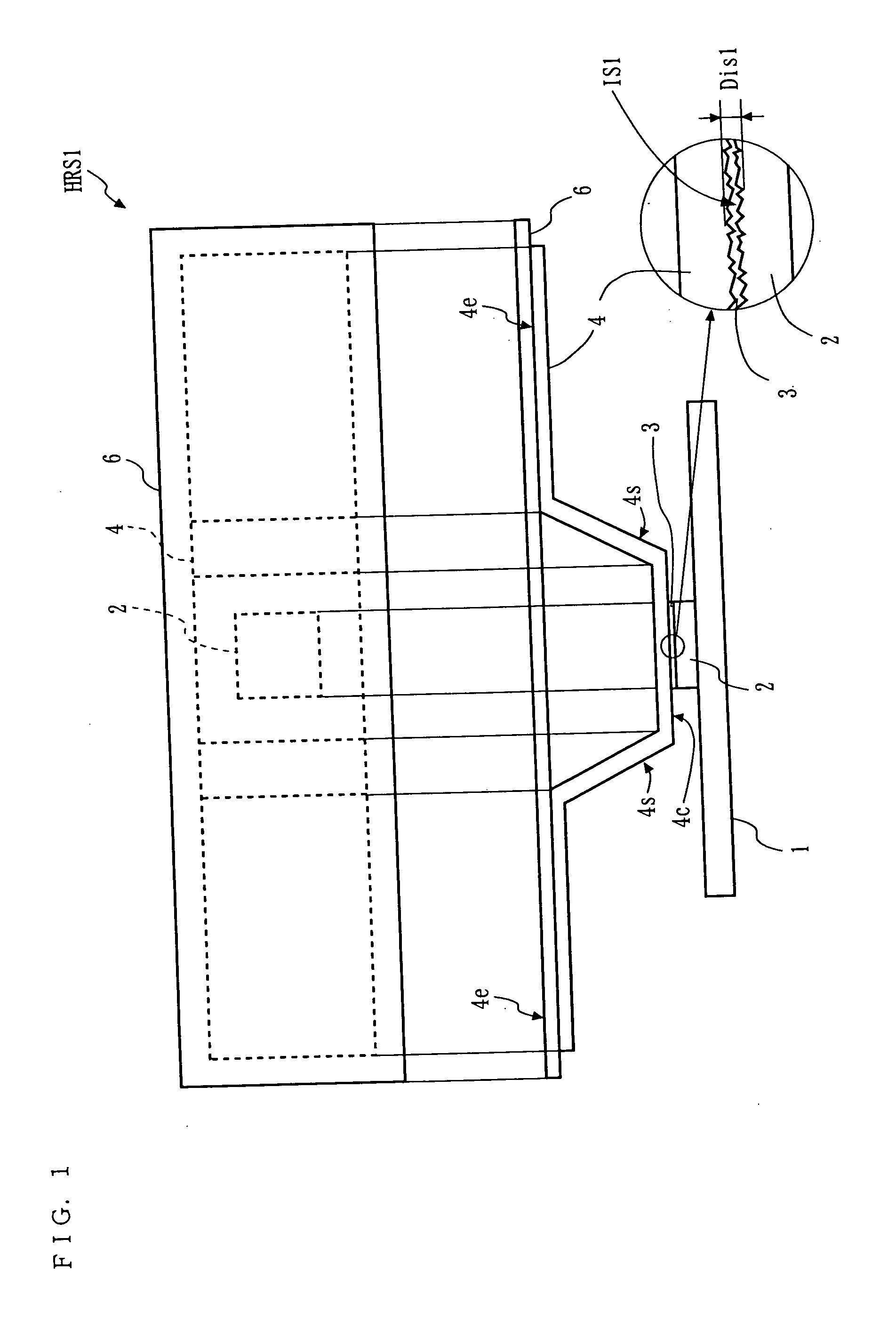
[0023] A heat-radiating mechanism and a heat-radiating structure of an electronic apparatus of the first embodiment of the present invention will be described with reference to FIG. 1. FIG. 1 shows a state viewed from the side of a heat-radiating mechanism constituted inside a notebook-type personal computer as an example of an electronic apparatus. It should be noted that members that are irrelevant to the heat-radiating mechanism such as a housing and a power source, are not shown.

[0024] In the notebook-type personal computer of this example, a heat-radiating grease 3 is applied to a CPU 2, which is a heat-generating component mounted in a print wiring board 1. Thereafter, a flexible graphite sheet 4 having a high thermal conductivity in the plane direction is thermally connected thereto in a such a manner that the lower surface of its central portion 4c that is obtained by folding the sheet with steps is attached in a non-fixed manner, and the upper surface of both end portions ...

second embodiment

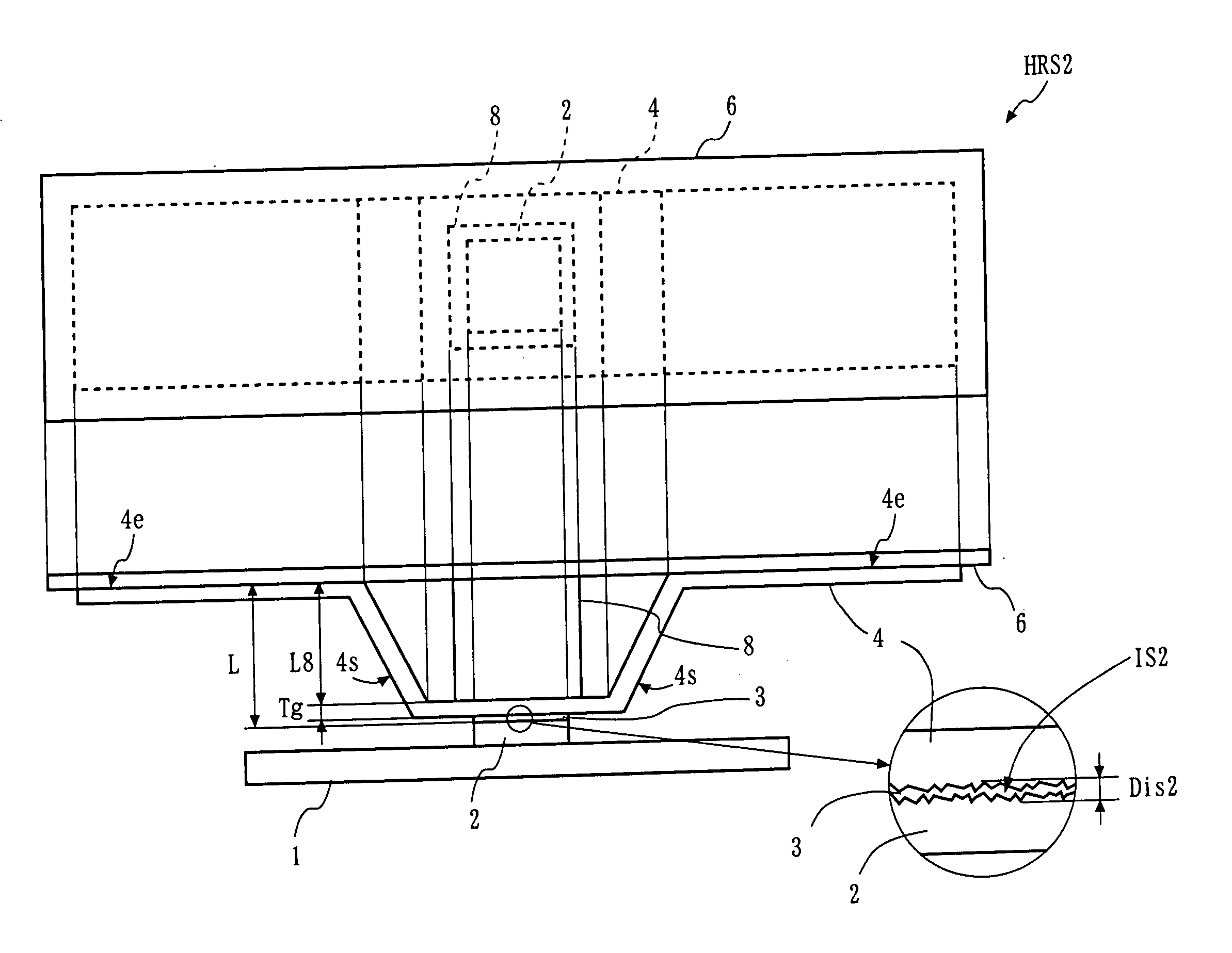
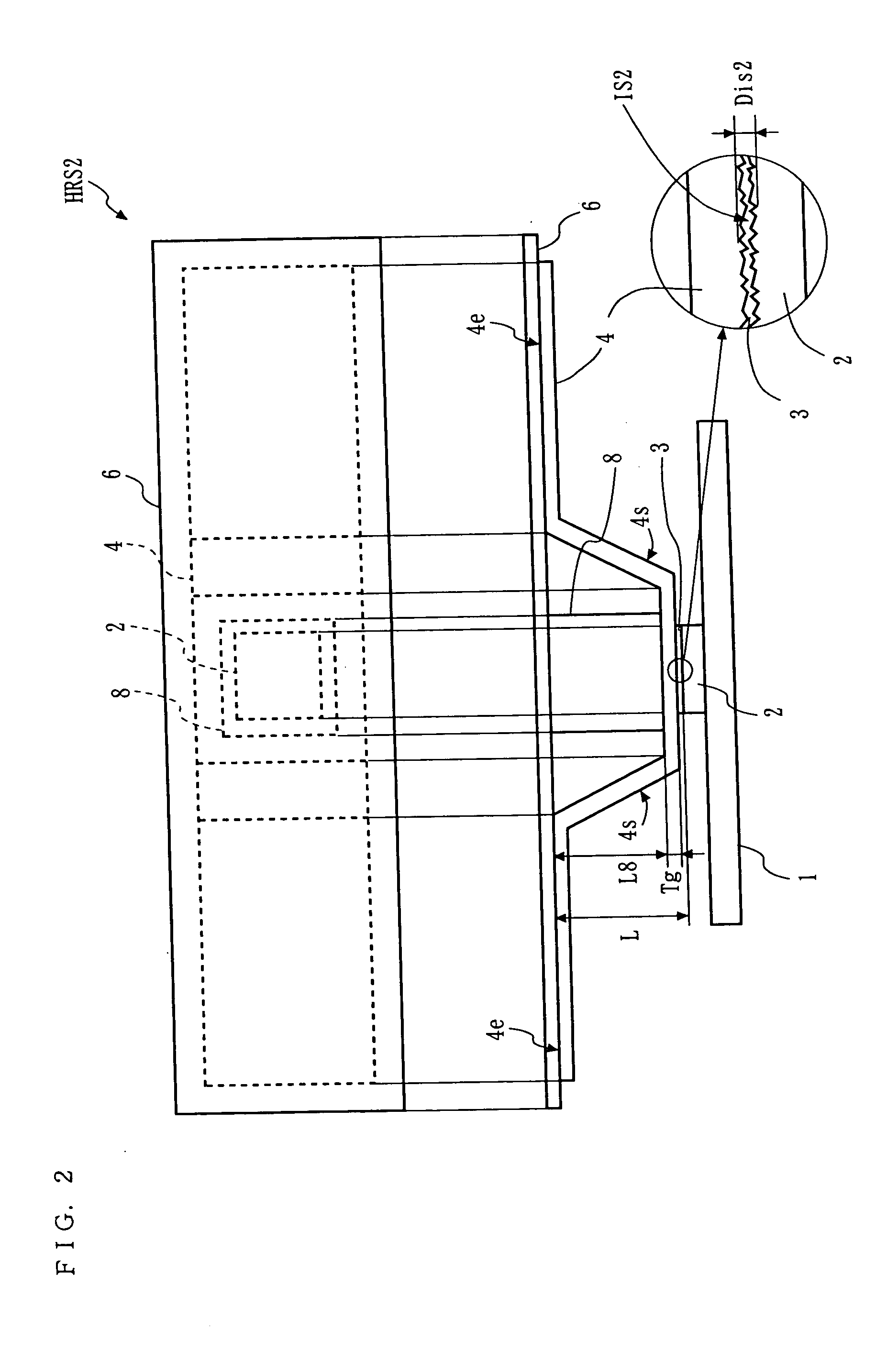
[0036] The heat-radiating mechanism of an electronic apparatus of a second embodiment of the present invention will be described with reference to FIG. 2. Similarly to in FIG. 1, FIG. 2 shows a state viewed from the side of the heat-radiating mechanism configured inside a notebook-type personal computer as an example of an electronic apparatus. A heat-radiating structure HRS2 of this embodiment is configured by adding an elastic member 8 to the heat-radiating structure HRS1 shown in FIG. 1. In this embodiment, a space (clearance) between the graphite sheet 4 and the CPU 2 is referred to as “thermal conduction resistance space IS2”. The distance in which the graphite sheet 4 is spaced apart from the CPU 2 is referred to as “resistance distance Dis2”, and the area in which the thermal conduction resistance space IS2 is present in the direction parallel to the graphite sheet 4 and the CPU 2 is referred to as “resistance area Ais2”. The size of the thermal conduction resistance space IS...

third embodiment

[0048] The heat-radiating mechanism of an electronic apparatus of a third embodiment of the present invention will be described with reference to FIG. 4. Similarly to in FIG. 1, FIG. 3 shows a cross section of the heat-radiating mechanism configured inside a notebook-type personal computer as an example of an electronic apparatus. A heat-radiating structure HRS3 of this embodiment is obtained by replacing the graphite sheet 4 in the heat-radiating structure HRS1 shown in FIG. 1 by a graphite multilayered sheet 14. In this embodiment, a space (clearance) between the graphite multilayered sheet 14 and the CPU 2 is referred to as “thermal conduction resistance space IS3” (not shown). The distance in which the graphite multilayered sheet 14 is spaced apart from the CPU 2 is referred to as “resistance distance Dis3” (not shown), and the area in which the thermal conduction resistance space IS3 is present in the direction parallel to the graphite multilayered sheet 14 and the CPU 2 is ref...


PUM


Abstract

In a heat-radiating structure HRS1 in which heat generated in a heat-generating component 2 built in a housing of an electronic apparatus is conducted to the outside, the central portion 4c of a flexible graphite sheet 4 that is folded and shaped so as to be elastic is thermally connected to the heat-generating component 2, and a flexible conductive member 3 is applied to a portion in which the central portion 4c is thermally connected to the heat-generating component 2.

Description

BACKGROUND OF THE INVENTION [0001] 1. Field of the Invention [0002] The present invention relates to a heat-radiating mechanism of a portable electronic apparatus including a notebook-type personal computer as a typical example. More specifically, the present invention relates to a heat-radiating structure. [0003] 2. Description of the Background Art [0004] Referring to FIG. 7, a heat-radiating mechanism of a conventional portable electronic apparatus will be described by taking a notebook-type personal computer as an example. In notebook-type personal computers, a heat-radiating plate 53 made of copper or aluminum having a thickness from about 0.5 mm to 2.0 mm is tightly attached to a CPU 2, which is a heat-generating component mounted in a print wiring board 51 to release and radiate heat generated in the CPU 2 to the outside via a heat-radiating plate 53. When sufficient heat radiation is not expected with such a structure, a portion of the heat-radiating plate 53 is brought in c...

Claims


Application Information

Patent Timeline
Patent Type & Authority Applications(United States)
IPC IPC(8): G06F1/20H01L23/367H01L23/373H05K7/20
CPCG06F1/203H01L23/367H01L23/373H01L2924/0002H01L2924/00
Inventor FUJIWARA, NORIO
Owner PANASONIC CORP
Why Eureka
Try Eureka