Optical pickup actuator

a technology of optical pickup actuators and actuators, which is applied in the direction of instruments, disposition/mounting of heads, record information storage, etc., can solve the problems of difficult to fix the wires to the tension parts of the pcb through soldering, and frequent deformation due to subsidiary resonan

Inactive Publication Date: 2005-06-16
SAMSUNG ELECTRO MECHANICS CO LTD
View PDF13 Cites 8 Cited by
  • Summary
  • Abstract
  • Description
  • Claims
  • Application Information

AI Technical Summary

Benefits of technology

[0026] Accordingly, the present invention has been made keeping in mind the above problems occurring in the prior art, and an object of the present invention is to provide an optical pickup actuator, which prevents tension parts from being vibrated when wires are fixed to the tension parts of a PCB through soldering, thus enabling the wires to be fixed at the exact locations of the tension parts.

Problems solved by technology

For slim-type or portable-type optical recording and reproducing apparatuses, in the optical pickup actuators thereof, the central points of an object lens and a driving force do not coincide with each other due to the structural characteristics of the optical pickup actuators, so that defects due to subsidiary resonance frequently occur.
Actually, because serious problems due to the subsidiary resonance defects occur at the time of production, measures to cope with the subsidiary resonance defects are required.
The conventional optical pickup actuator, constructed and operated as described above, is problematic in that it is difficult to fix the wires to the tension parts of the PCB through soldering and to keep the gaps uniform between the magnets and the coils.
Further, the conventional optical pickup actuator is problematic in that a case where the wires are not fixed at exact locations frequency occurs due to differences between the times required for solder applied on the four tension parts to solidify, in addition to the vibration of the tension parts at the time of soldering.
As described above, the conventional optical pickup actuator is problematic in that, as a total of four wires are fixed to the corresponding tension parts through soldering, a position error is generated, so that the position of the bobbin supported by the wires is changed and offset, thus varying the gaps between the coils and the magnets.

Method used


Image

  • Optical pickup actuator
  • Optical pickup actuator
  • Optical pickup actuator

Examples


Embodiment Construction

[0050] Hereinafter, embodiments of the present invention will be described in detail with reference to the attached drawings.

[0051] Reference now should be made to the drawings, in which the same reference numerals are used throughout the different drawings to designate the same or similar components.

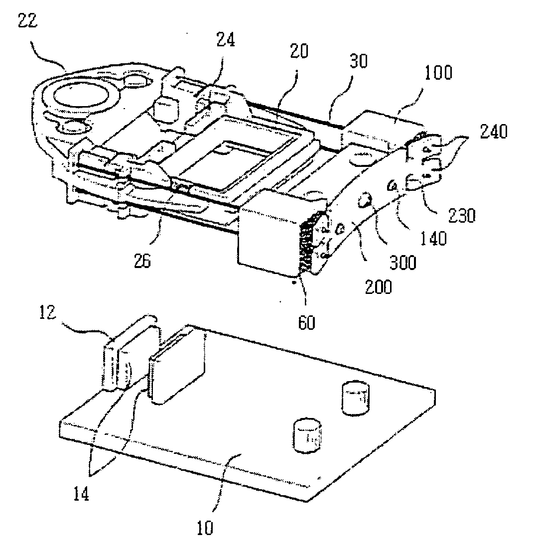
[0052]FIG. 4 is an exploded perspective view of an optical pickup actuator according to the present invention, FIG. 5 is a top view showing the optical pickup actuator of the present invention, and FIG. 6 is a view showing an assembly process to describe a method of adjusting and fixing the positions of wires of the present invention.

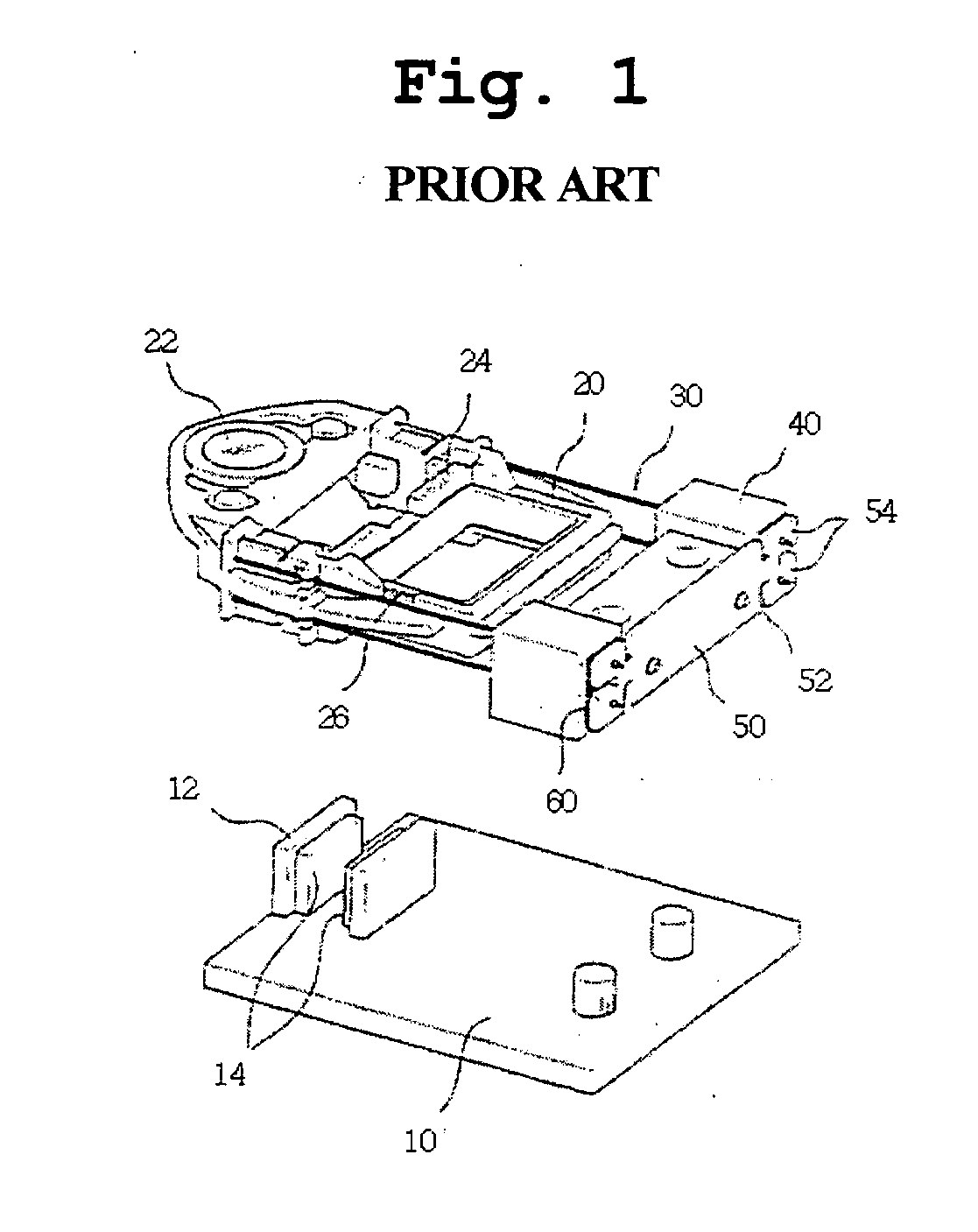
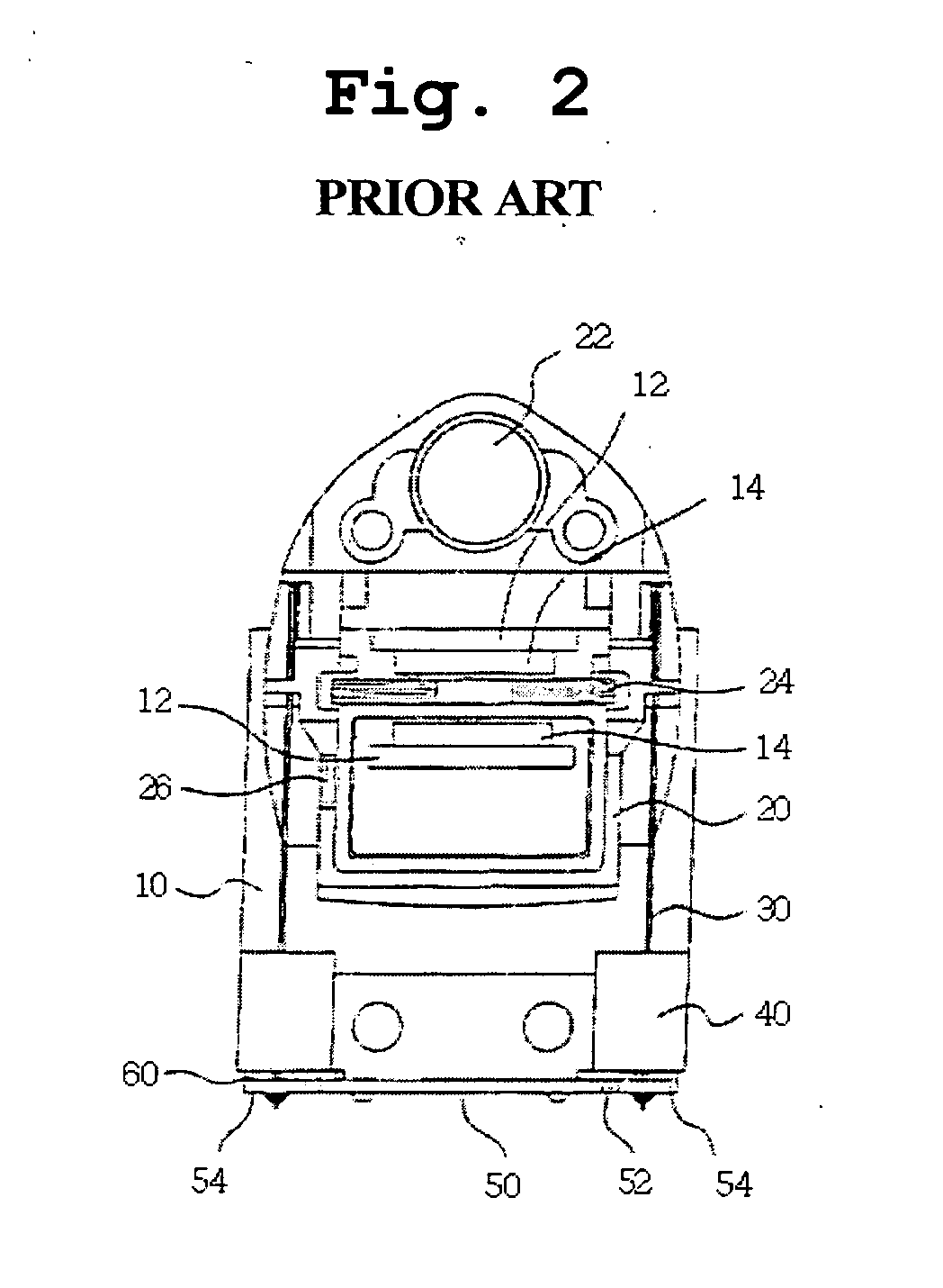
[0053] Referring to FIGS. 4 to 6, in the optical pickup actuator of the present invention, a bobbin 20 provided with an object lens 22 is installed on a support plate 10 so that the position of the bobbin 20 can be finely adjusted in a focusing direction, that is, a vertical direction, and in a tracking direction, that is, a horizontal direction.

[0054] ...


PUM

PropertyMeasurementUnit
tensionaaaaaaaaaa
distanceaaaaaaaaaa
Tensionaaaaaaaaaa

Abstract

The present invention relates, in general, to an optical pickup actuator and, more particularly, to an optical pickup actuator, in which a depression (120) is formed in a center portion of a rear surface of a wire holder (100) to be depressed, and the position of a bobbin (20) is adjusted by straining wires (30) while a center portion of a printed circuit board (200), closely attached to the rear surface of the wire holder, is pressurized using a control screw (300) to allow the printed circuit board to be arcuately deformed.

Description

BACKGROUND OF THE INVENTION [0001] 1. Field of the Invention [0002] The present invention relates, in general, to optical pickup actuators and, more particularly, to an optical pickup actuator, which improves the structures of a holder and a printed circuit board to which wires are fixedly attached, so that the wires can be soldered at exact locations, and so that gaps between magnets and coils can be adjusted through the adjustment of the positions of the wires, thus keeping the gaps uniform. [0003] 2. Description of the Related Art [0004] Generally, an optical pickup is a device mounted on both a main shaft and a sub-shaft provided on a deck of an optical recording and reproducing apparatus to record signals on a variety of optical disks or reproduce the signals recorded on the optical disks while reciprocating along an axial direction. Typically, the optical pickup is divided into a pickup base and an actuator. [0005] The pickup base is directly mounted on both the main shaft and...

Claims


Application Information

Patent Timeline
Patent Type & Authority Applications(United States)
IPC IPC(8): G11B7/08G11B7/00G11B7/085G11B7/09G11B7/22H05K1/02H05K3/34
CPCG11B7/0932G11B7/0933G11B7/22H05K1/0271H05K3/3447H05K2201/09018H05K2201/2045H05K2201/1003H05K2201/10409H05K2201/10424H05K2201/10598H05K2201/10977H05K2201/09063G11B7/0946G11B7/085
Inventor WON, SUNG-HONGKIM, DONG-WOOHNCHOI, CHANG-HWAN
Owner SAMSUNG ELECTRO MECHANICS CO LTD
Why Eureka
Try Eureka