Optical disc system and associated tilt angle calibration method

a technology of optical discs and tilt angles, applied in the field of optical disc systems, can solve the problems of lowering the quality of the optical disc system, difficult to perfectly align these two light beams, and the inability of the optical sensor to accurately reproduce encoded data

Inactive Publication Date: 2005-06-16
MEDIATEK INC
View PDF6 Cites 42 Cited by
  • Summary
  • Abstract
  • Description
  • Claims
  • Application Information

AI Technical Summary

Problems solved by technology

If the incident light beam on the surface of the optical disc is misaligned relative to the disc surface, it may be impossible for the optical sensor to accurately reproduce the encoded data.
If the alignment is close but still incorrect, increased data errors and clock jitter in the received data stream will lower the quality of the optical disc system.
However, it is often difficult to perfectly align these two light beams.
Using a separate light beam and sensor pair, which must themselves be properly aligned, to correct an alignment problem is not an optimal solution.
However, using the jitter meter significantly increases the complexity of the design and requires extra components such as the jitter meter to be added to the optical disc system.
This optical disc system, however, again requires additional hardware components and increased design complexity, increasing the overall cost of the optical disc system.

Method used


Image

  • Optical disc system and associated tilt angle calibration method
  • Optical disc system and associated tilt angle calibration method
  • Optical disc system and associated tilt angle calibration method

Examples


Embodiment Construction

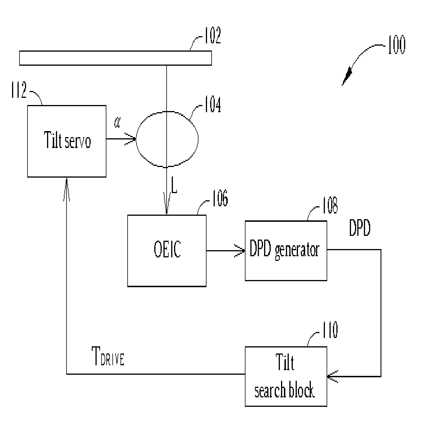
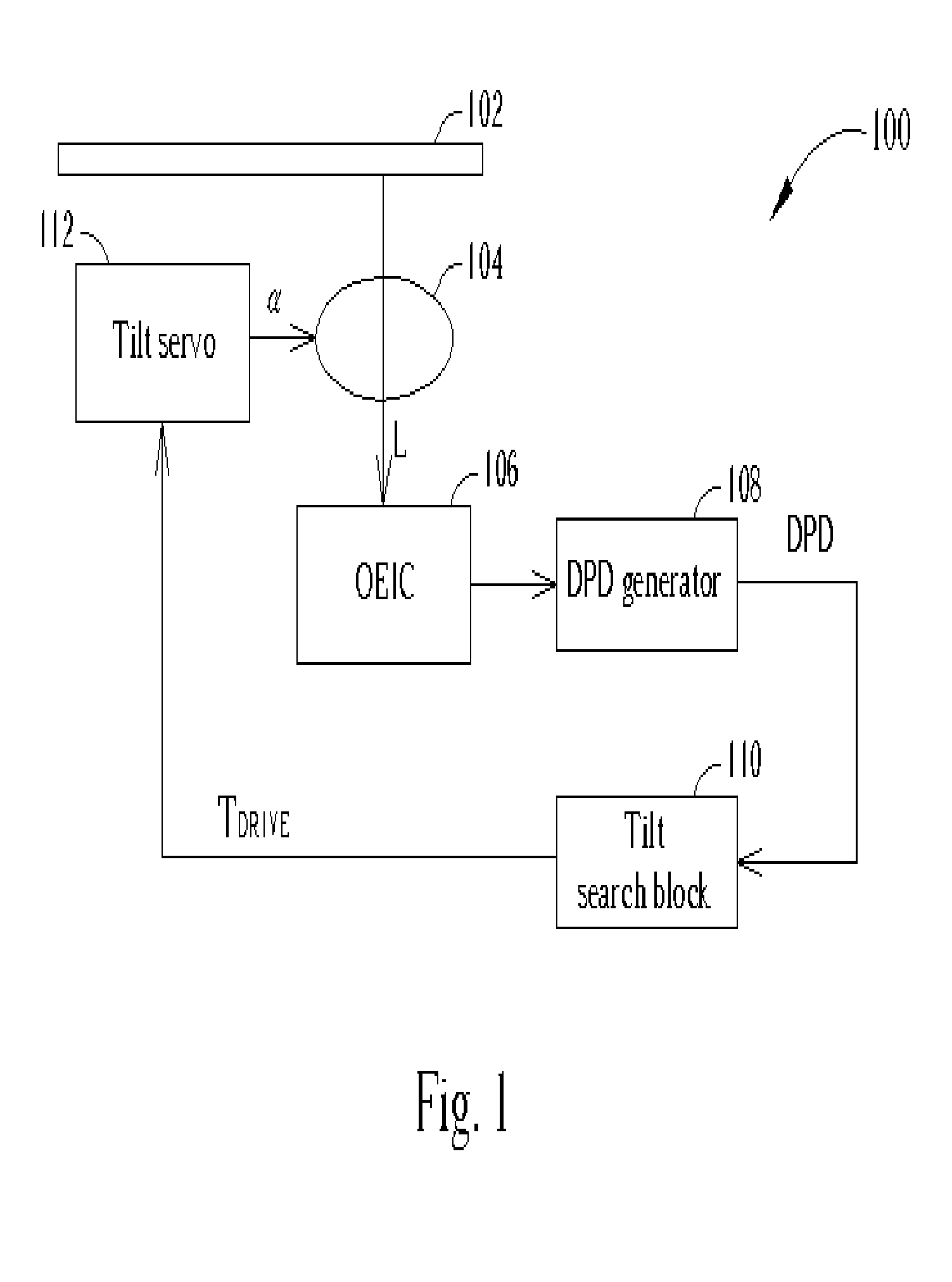
[0020]FIG. 1 shows a block diagram of an optical disc system 100 according to the first embodiment of the present invention. The optical disc system 100 comprises an optical disc 102, an object lens 104, an optical electrical integrated circuit (OEIC) 106, a differential phase detection (DPD) signal generator 108, a tilt search block 110, and a tilt servo 112. Incident light is reflected off the optical disc 102 at a tilt angle controlled by the tilt servo 112. The tilt servo 112 receives a control signal TDRIVE from the tilt search block specifying a tilt angleα between the optical disc 102 and the object lens 104. The tilt servo 112 controls the tilt angleα. Reflected light L passes through the object lens and is detected by the OEIC 106. The OEIC 106 is an optical sensor that generates electrical signals according to the reflected light L. The DPD signal is a common signal required in optical disc systems and the DPD signal generator 108 generates this DPD signal according to the...


PUM

PropertyMeasurementUnit
tilt angleaaaaaaaaaa

Abstract

A controllable tilt servo adjusts a tilt angle between an optical disc and an object lens according to a control signal from a CPU. An optical electric integrated circuit (OEIC) generates a differential phase detection (DPD) signal according to light received through the object lens from the optical disc. A tilt search block receives the DPD signal and controls the tilt servo by adjusting the tilt angle between the optical disc and the object lens according to the DPD signal. By iteratively scanning pluralities of tilt angles, each plurality of angles having decreasing angle differences and being centered on the tilt angle having the lowest amplitude DPD signal, an optimal tilt angle having the lowest amplitude DPD signal can be found.

Description

BACKGROUND OF INVENTION [0001] 1. Field of the Invention [0002] The invention relates to an optical disc system, and more particularly, to an optical disc system capable of calibrating the tilt angle between an optical disc and an object lens. [0003] 2. Description of the Prior Art [0004] Optical discs are well suited for storing large amounts of data and have a long lifetime. For these reasons, optical discs are widely used in today's ever increasingly computerized society. Optical discs do not suffer from magnetic deterioration over time as do magnetic media types. Compact discs (CDs), compact disc read only memories (CD-ROMs), digital versatile discs (DVDs), and various types of writable versions of these formats are all commonly used today. Although differing in physical form and digital format, in general, all optical disc systems project a beam of light on an optical disc through an object lens. This light is reflected off the optical disc and detected by an optical detector. ...

Claims


Application Information

Patent Timeline
Patent Type & Authority Applications(United States)
IPC IPC(8): G11B7/09G11B7/095
CPCG11B7/0956
Inventor TSAI, MING-HSIEN
Owner MEDIATEK INC
Why Eureka
Try Eureka