
Switch capable of controlling data packet transmission and related method

a technology of data packet transmission and controller, which is applied in the direction of data switching network, digital transmission, electrical equipment, etc., can solve the problems of router not being able to replace the switch or the hub, the mac address field cannot be analysed, and the cost and complexity of the router are high, so as to reduce the cost and simplify the operation.

Inactive Publication Date: 2005-06-16
VIA TECH INC
View PDF6 Cites 18 Cited by
  • Summary
  • Abstract
  • Description
  • Claims
  • Application Information

AI Technical Summary

Benefits of technology

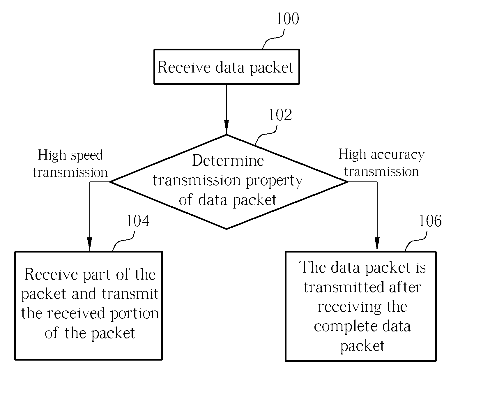
[0017] In determining the property of the data packet transmission in the claimed invention, which is basically differentiating whether the data packet requires a high-speed transmission requirement or a high-accuracy transmission requirement. The store-and-forward mode ensures the accuracy of the data packet received by the switch, and the cut-through mode ensures a faster speed of data packet received by the switch. Therefore when the high-speed transmission requirement is needed, the claimed invention uses the cut-through mode, and when the high-accuracy transmission requirement is needed, the claimed invention then uses the store-and-forward mode.
[0019] According to another advantage of the claimed invention, the switch is capable of determining the property of the data packet transmission through analyzing content of a particular byte of the data packet to change the output mode of the queue buffer. Also, unlike the router, the claimed invention does not need to change the header of the data packet, hence simplifying operation and reducing cost.

Problems solved by technology

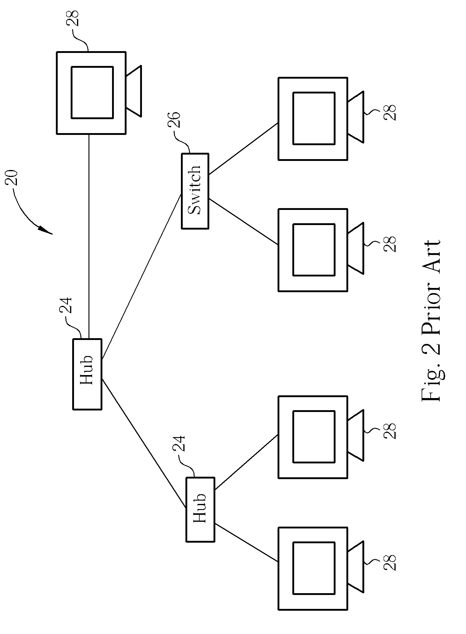
However, the hub 24 operates at a physical level of the OSI and is unable to analyze the MAC address field of the data link layer packet header.
In this way, cost and complexity of the router is high, and under commercial considerations the router cannot replace the switch or the hub.
It is obvious that those skilled in the art will recognize that the switch is unable to differentiate whether the data packet transmission requires an accurate transmission or time efficient transmission, and hence cannot find the best possible transmission according to the transmission property of the received data packet.
Besides, for the router, the data packet usually needs to be resolved to the third layer and therefore the processing time and cost is increased.

Method used


Image

  • Switch capable of controlling data packet transmission and related method
  • Switch capable of controlling data packet transmission and related method
  • Switch capable of controlling data packet transmission and related method

Examples


Embodiment Construction

[0029] Please refer to FIG. 4. FIG. 4 illustrates a diagram of a switch 30b, a source end 40a, and destination end 40b. Both the source end 40a and destination end 40b can be a client, a router, a hub, or another switch. The switch comprises one or more input port 32b for receiving a data packet from the source end 40a, one or more output ports 34b for outputting a data packet to the destination end 40b, one queue buffer 38b for temporarily storing a data packets received by the input port 32, and one analyzing processing unit 36b for selecting the mode of processing the data packet by the queue buffer 38b and the output port 34b according to the transmission property at least part of the data packet stored in the queue buffer 38b.

[0030] The present invention determines whether the transmission property of the data packet is a high-speed transmission requirement or a high-accuracy transmission requirement. In a more detailed explanation, based on the content of the data packet, the...


PUM


Abstract

A switch capable of controlling data packet transmission includes at least one input port for receiving a data packet, at least one output port for outputting the data packet, a queue buffer for holding the received data packet, and a analyzing-processing unit for determining how to transmit the received data packet based on a transmission requirement of the received data packet.

Description

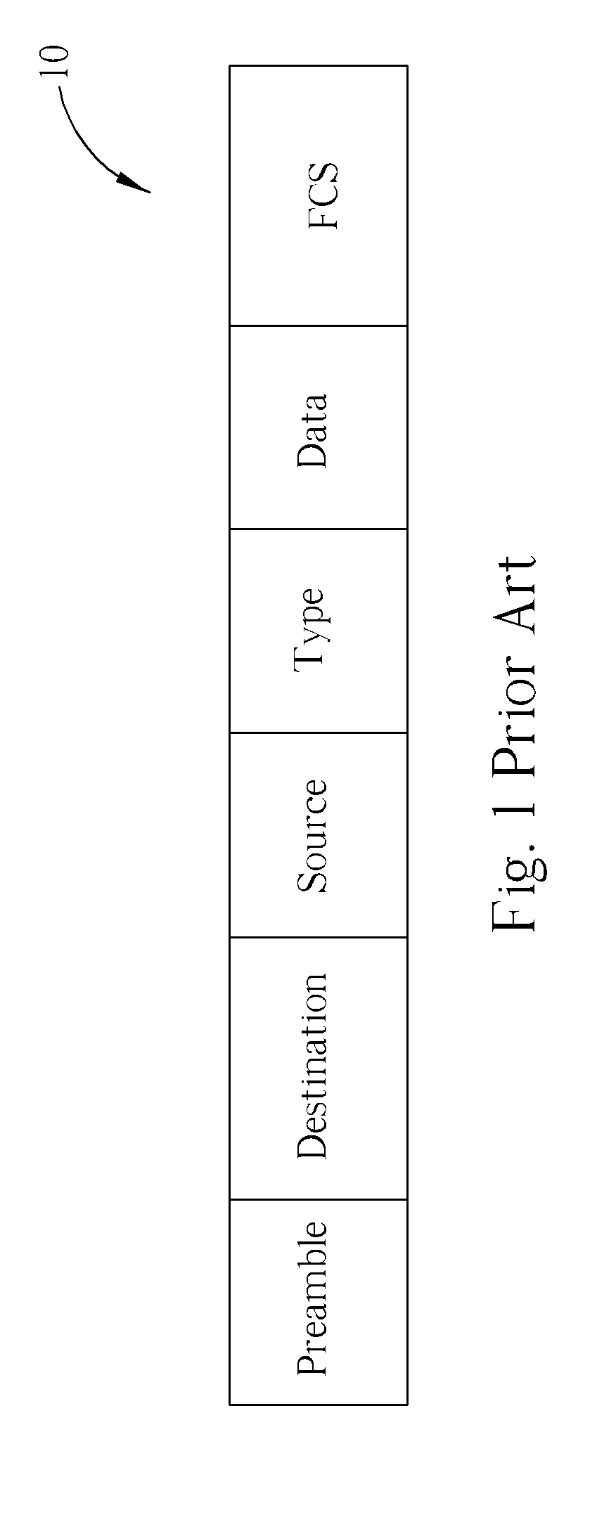
CROSS REFERENCE TO RELATED APPLICATIONS [0001] This application claims the benefit of U.S. Provisional Application No. 60 / 481,778, filed Dec. 12, 2003, and included herein by reference.BACKGROUND OF INVENTION [0002] 1. Field of the Invention [0003] The present invention relates to a switch capable of controlling data packet transmission, more particularly, to a switch capable of controlling data packet transmission according to a high-speed transmission requirement and a high-accuracy transmission requirement. [0004] 2. Description of the Prior Art [0005] As applications of networks flourish, personal users and companies rely more and more on networks today, especially Ethernet. The International Organization for Standardization (ISO) provides an open system interconnect mode (OSI) which can be accessed by the public. Standard network transmission uses a common mode in which there are seven levels of communication mode. The seven levels allow correspondence such as transmission, rec...

Claims


Application Information

Patent Timeline
IPC IPC(8): H04L12/56
CPCH04L45/40H04L47/10H04L47/122H04L47/18H04L47/2408H04L49/20H04L49/9089H04L49/252H04L49/3009H04L49/351H04L49/602H04L49/90H04L49/251
Inventor KU, HAU-CHUNCHEN, WEIPINLIN, RUTHCHENG, CHAOCHENG
Owner VIA TECH INC
Learn More