
Channel equalizing device and method of digital broadcasting receiving system

a technology of digital broadcasting and equalizing devices, applied in the field of digital broadcasting receiving systems, to achieve the effect of improving channel characteristic detection capability and equalizing performan

Inactive Publication Date: 2005-06-16
LG ELECTRONICS INC
View PDF3 Cites 33 Cited by
  • Summary
  • Abstract
  • Description
  • Claims
  • Application Information

AI Technical Summary

Benefits of technology

[0015] An object of the present invention is to provide a channel equalizing device and method of a digital broadcasting receiving system in which an estimated channel impulse response is used to determine as to whether a channel characteristic is a dynamic channel or a static channel and control a parameter of a channel equalizer suitably to the determined channel characteristic, thereby improving a performance of channel equalization.
[0018] The channel estimating unit estimates the channel impulse response every field by using a training sequence included in a field synchronization signal whenever the field synchronization signal is inputted. Additionally, if the decision values are used as a training sequence, then the channel impulse response can be estimated during a data segment period as well as a field synchronization segment period. The channel estimation using a decision value enables more frequent channel estimation and it can be used to improve channel characteristic detection capability and equalizer performance.

Problems solved by technology

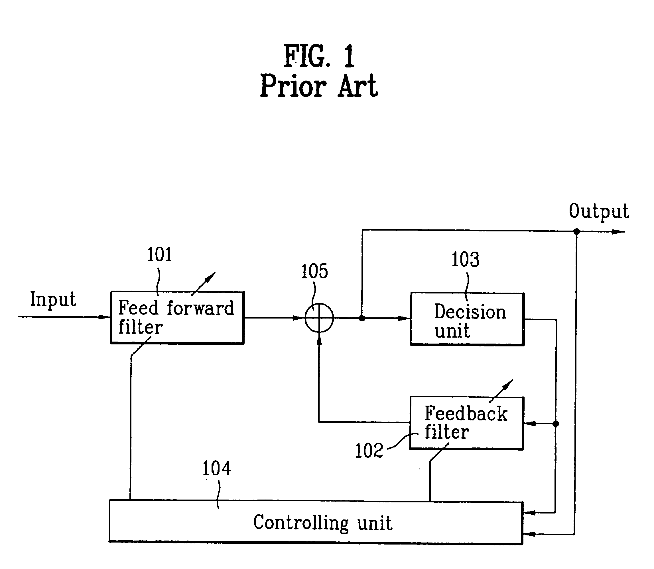
While the signal reaching the receiving system (that is, ATSC 8T-VSB receiving system) passes through a multi-path transmission channel, it causes an inter-symbol-interference.

Method used


Image

  • Channel equalizing device and method of digital broadcasting receiving system
  • Channel equalizing device and method of digital broadcasting receiving system
  • Channel equalizing device and method of digital broadcasting receiving system

Examples


Embodiment Construction

[0039] Reference will now be made in detail to the preferred embodiments of the present invention, examples of which are illustrated in the accompanying drawings. Wherever possible, the same reference numbers will be used throughout the drawings to refer to the same or like parts.

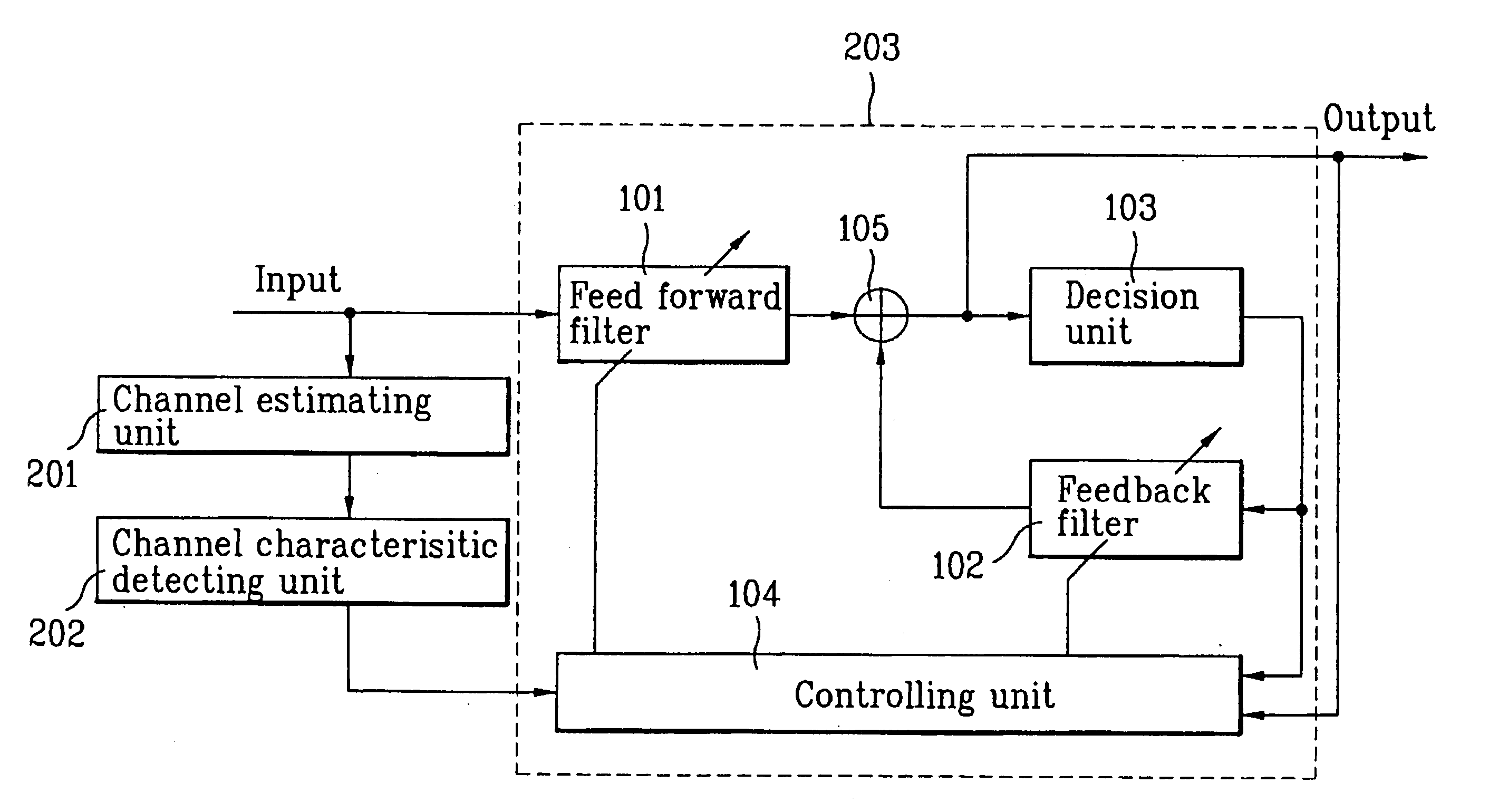
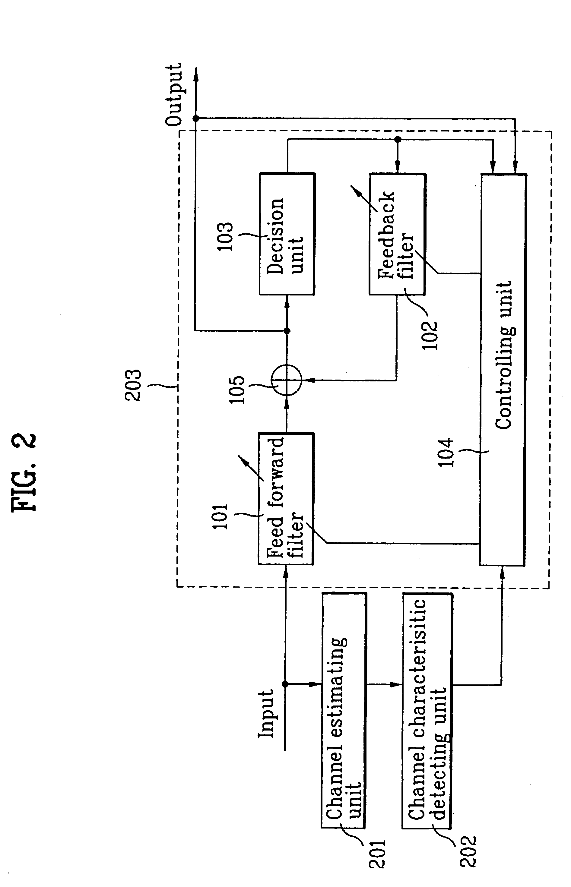
[0040] The present invention is characterized in that a channel impulse response is estimated at each field synchronization signal periodically received, and the estimated previous impulse response and current impulse response are used to measure a degree of channel variation. Additionally, on the basis of the measured degree of the channel variation, it is determined as to whether the channel characteristic is the dynamic channel or the static channel and then, a parameter of a channel equalizer is controlled suitably to the determined channel characteristic.

[0041]FIG. 2 is a block diagram illustrating a channel equalizing device according to the present invention.

[0042] The channel equalizing device in...


PUM


Abstract

A channel equalizing device and method of a digital broadcasting receiving system in which a digital broadcasting signal received over a channel is compensated for a channel distortion to recover an original signal is provided. The channel equalizing device includes: a channel estimating unit for estimating and outputting a channel impulse response of a signal, which is received over a transmission channel; a channel characteristic detecting unit for determining as to whether a channel characteristic is a dynamic channel or a static channel by using a difference between the channel impulse response estimated at a current time and outputted from the channel estimating unit and the channel impulse response estimated at a previous time; and a channel equalizing unit for controlling a parameter of an internal filter depending on the channel characteristic detected by the channel characteristic detecting unit, to compensate the received signal for the channel distortion.

Description

[0001] This application claims the benefit of the Korean Application No. 10-2003-0090703 filed on Dec. 12, 2003, which is hereby incorporated by reference. BACKGROUND OF THE INVENTION [0002] 1. Field of the Invention [0003] The present invention relates to a digital broadcasting receiving system, and more particularly, to a channel equalizing device and method of a terrestrial digital TV signal transmitted using a Vestigial Side Band (VSB) technology. [0004] 2. Discussion of the Related Art [0005] In U.S.A., ATSC 8T-VSB transmission system is adopted and standardized in 1995 to provide a terrestrial digital broadcasting from the latter half of 1998 until now. In South of Korea, the same ATSC 8T-VSB transmission system as in U.S.A. is adopted and standardized to provide an experimental broadcasting on May 1995, and is converted into a test broadcasting system on Aug. 31, 2000, and is under broadcasting at each broadcasting service corporation since October, 2000. [0006] Additionally,...

Claims


Application Information

Patent Timeline
Patent Type & Authority Applications(United States)
IPC IPC(8): H04N7/015H03G11/04H03K5/159H04L25/02H04L25/03H04L27/01
CPCH04L25/0202H04L25/0222H04L25/03057H04L2025/03726H04L2025/0349H04L2025/03694H04L2025/03375H04N7/015
Inventor KANG, KYUNG WONCHOI, IN HWAN
Owner LG ELECTRONICS INC
Learn More