Telephone headset with in-use indicator

a technology of in-use indicators and headsets, applied in the direction of loudspeakers, piezoelectric/electrostrictive transducers, transducer types, etc., can solve the problems of affecting the use of headsets, avoiding direct communication, and wasting a large amount of time on the telephone, so as to increase visibility, add significant weight to headsets, and avoid adverse effects on headset users

Inactive Publication Date: 2005-06-16
GARNER CLINT D
View PDF6 Cites 41 Cited by
  • Summary
  • Abstract
  • Description
  • Claims
  • Application Information

AI Technical Summary

Benefits of technology

[0015] More specifically, it is an object of the present invention to provide a telephone headset having an in-use indicator that uses strategically placed lighting to indicate that the headset is in use without adversely affecting the headset user.
[0016] It is a further object of the present invention to provide an in-use indicator for telephone headsets that is highly visible from multiple angles, that does not require large amounts of power or add significantly to a headset's weight, that uses a flashing light to increase visibility, and that allows the headset to be cost competitive with other sets on the market.
[0017] It is a further object of the present invention to provide a telephone headset having an in-use indicator that is simpler, more compact, and more intuitive than a separate unit.
[0018] It is a further object of the present invention to provide an in-use indicator for a telephone headset that provides an interesting visual effect by altering the flashing light dependent on the volume of incoming or outgoing sound.
[0021] According to another broad aspect of the present invention, a telephone headset is provided, comprising: a support structure for supporting the headset hands-free on a user's head; and a boom connected to the support structure for positioning a microphone near a user's mouth. The boom has a side facing away from the user's head and a groove formed in said side. At least one light source is positioned in the groove on the boom and arranged such that the light source is completely shielded from the user's eyes to provide an in-use indicator for the headset that does not bother the user.

Problems solved by technology

More than ever before, this means spending large amounts of time on the telephone.
Although telephone headsets have made this level of phone time tolerable, our “phone etiquette” has yet to account for the use of headsets—particularly in an office environment.
Also, if the colleague is wearing a headset, others may forgo direct communication thinking that the colleague is in the middle of a telephone conversation, even when he or she is not.
These prior art designs have certain shortcomings and disadvantages that appear to have limited their success and widespread adoption in the marketplace.
The use of a single LED prevents the indicator from being readily visible from the side or the back, making it ineffective for persons who are not located directly in front of the person wearing the headset.
However, the headset user is then exposed to the indicator light, which creates other adverse effects, particularly if a flasher circuit is employed.
The adverse effects if the headset user is exposed to a flashing in-use indicator light could range from annoyance to nausea.
The in-use indicator of Winegar protrudes above the headset making it more bulky and more likely to be bumped and otherwise interfere with the user's comfort while wearing the headset.
Also, having the in-use indicator positioned at the end of an extension member away from the headset is less intuitive making it less effective for those not familiar with its function.

Method used


Image

  • Telephone headset with in-use indicator
  • Telephone headset with in-use indicator
  • Telephone headset with in-use indicator

Examples


Embodiment Construction

[0033] A telephone headset having a lighted in-use indicator according to preferred embodiments of the present invention will now be described in detail with reference to FIGS. 1 to 6 of the drawings.

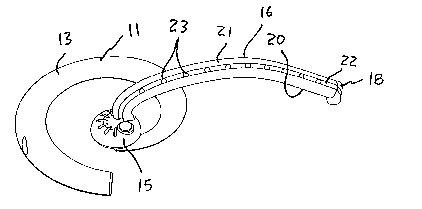
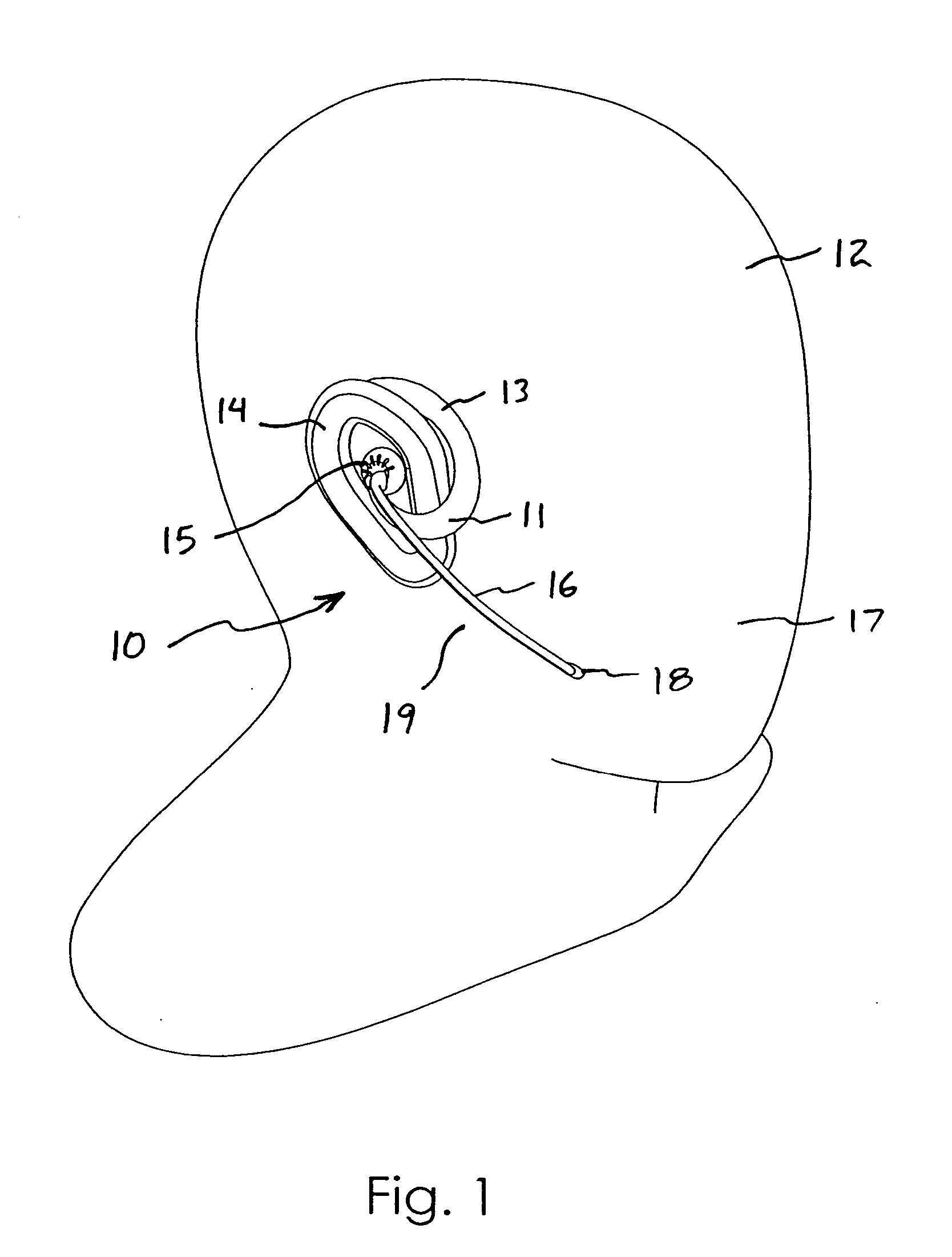
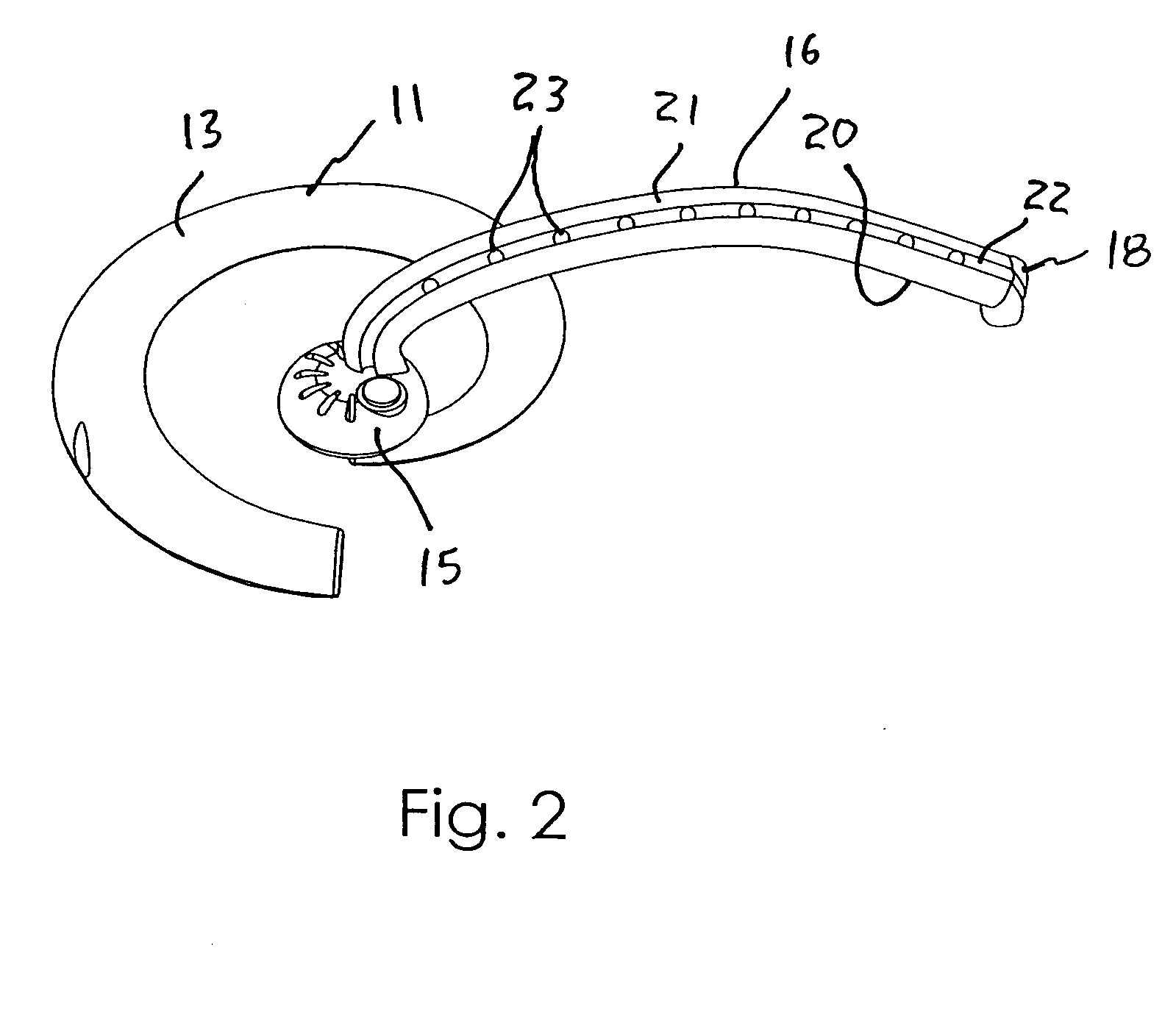
[0034] A first embodiment of the telephone headset 10 is shown in FIGS. 1 and 2. The headset 10 according to the first embodiment has a support structure 11 in the form of an ear-clip configuration for supporting the headset 10 hands-free on a user's head 12. The ear-clip configuration includes a curved member 13 that fits over and rests on the top of the user's ear 14.

[0035] An earpiece 15 is connected at one end of the curved member 13 for positioning a small speaker near the user's ear 14 for transmitting incoming sounds to the user's ear 14. The earpiece 15 can be formed integral with the curved member 13 or as a separate component. The term “support structure” is broadly used herein to refer to both the earpiece 15 and the structure 11 for supporting the headset 10 on the user's ...


PUM


Abstract

A telephone headset includes a support structure for supporting the headset hands-free on a user's head, an earpiece for transmitting sounds to a user's ear, and a boom having a first end connected to the support structure and a second end containing a microphone that can be positioned near a user's mouth. The boom has a side facing away from the user's head with a groove formed therein extending along a length of the boom. A plurality of LEDs are positioned in the groove and are spaced apart along the length of the boom. The LEDs are arranged in the groove so as to be completely shielded from the user's eyes when the headset is supported on the user's head. A control circuit with a flasher is provided for flashing the LEDs when the telephone is in-use. Variations of the light source, the control circuit, and the headset structure are disclosed.

Description

BACKGROUND OF THE INVENTION [0001] 1. Field of the Invention [0002] The present invention relates generally to telephone headsets that attach hands-free onto the head of a user. In particular, the present invention relates to telephone headsets having an in-use indicator thereon for indicating that the person wearing the headset is on the telephone. [0003] 2. Description of the Related Art [0004] A large portion of the workforce today is involved in the service industry. More than ever before, this means spending large amounts of time on the telephone. Although telephone headsets have made this level of phone time tolerable, our “phone etiquette” has yet to account for the use of headsets—particularly in an office environment. When using headsets, it is not obvious at a glance whether or not an officemate is engaged in a telephone conversation or available to speak with. The visual clues that warn us that a colleague is speaking on the telephone (e.g., a handheld receiver cradled ag...

Claims


Application Information

Patent Timeline
Patent Type & Authority Applications(United States)
IPC IPC(8): H04R1/10
CPCH04R1/083H04R1/10H04R2201/107H04R5/0335H04R29/008H04R1/105
Inventor GARNER, CLINT D.
Owner GARNER CLINT D
Why Eureka
Try Eureka