Inducer tip vortex suppressor

a technology of inducer and tip, applied in the field of fluid motivation, can solve the problems of large backflow through the tip clearance, unmet needs in the art, incidence angle sensitive, etc., and achieve the effect of eliminating the backflow of tip clearan

Inactive Publication Date: 2005-06-16
THE BOEING CO +1
View PDF5 Cites 17 Cited by
  • Summary
  • Abstract
  • Description
  • Claims
  • Application Information

AI Technical Summary

Benefits of technology

[0010] In accordance with still another aspect of the invention, the second flow is directed to energize a boundary layer flow. Advantageously, the energizing of the boundary layer flow is sufficient to eliminate a tip clearance back flow by optimizing the effective incidence angle at the inducer tip.

Problems solved by technology

The larger incidence angle results in a larger differential pressure across the blade tip near the leading edge, which, in turn, results in larger back flow through the tip clearance.
The dynamic instability only occurs within a limited flow rate verses speed range, which suggests that it is incidence angle sensitive.
Head break down results from blockage due to the cavitation sheet that originates on the suction side of the blade leading edge when the local static pressure falls below the propellant vapor pressure.
As a result, there is an unmet need in the art to minimize the tip vortex cavitation cavity by suppressing the back flow through the tip clearance.

Method used


Image

  • Inducer tip vortex suppressor
  • Inducer tip vortex suppressor
  • Inducer tip vortex suppressor

Examples


Embodiment Construction

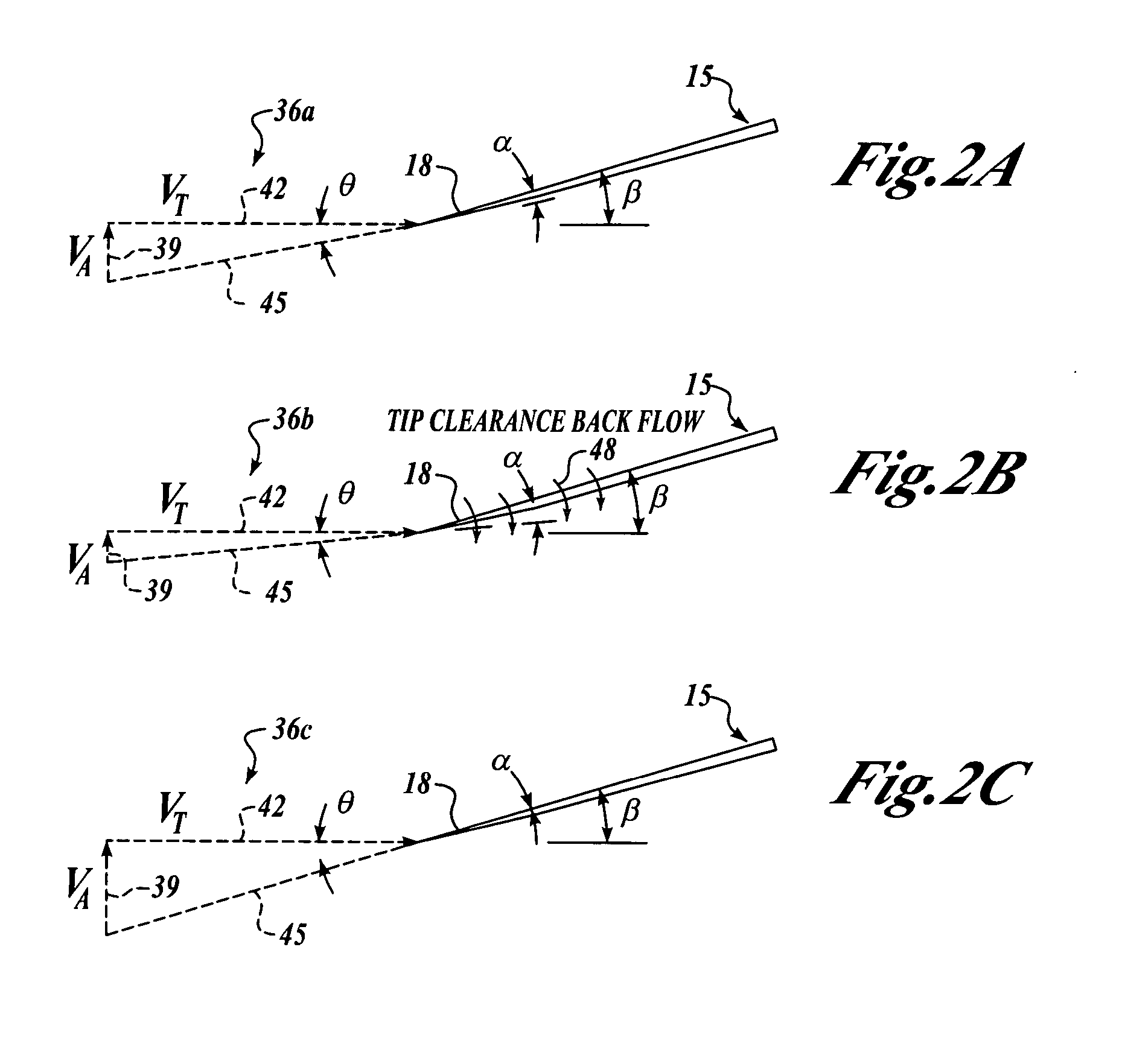
[0018] By way of overview, embodiments of the invention provide a method, device, and turbopump configured to suppress higher order cavitations at an inducer tip in a turbopump. An inducer having a tip is rotated at a tangential velocity and a first flow is induced axially through the inducer at a first axial velocity. A second fluid flow is introduced toward the tip clearance of the inducer substantially parallel to the first fluid flow at a second axial velocity that is greater than the first axial velocity, such that back flow through the tip clearance of the inducer is reduced.

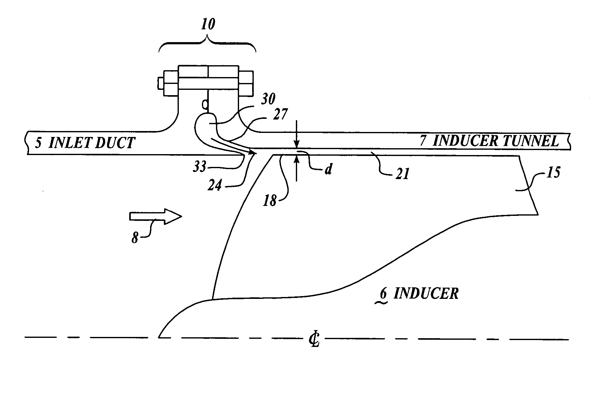
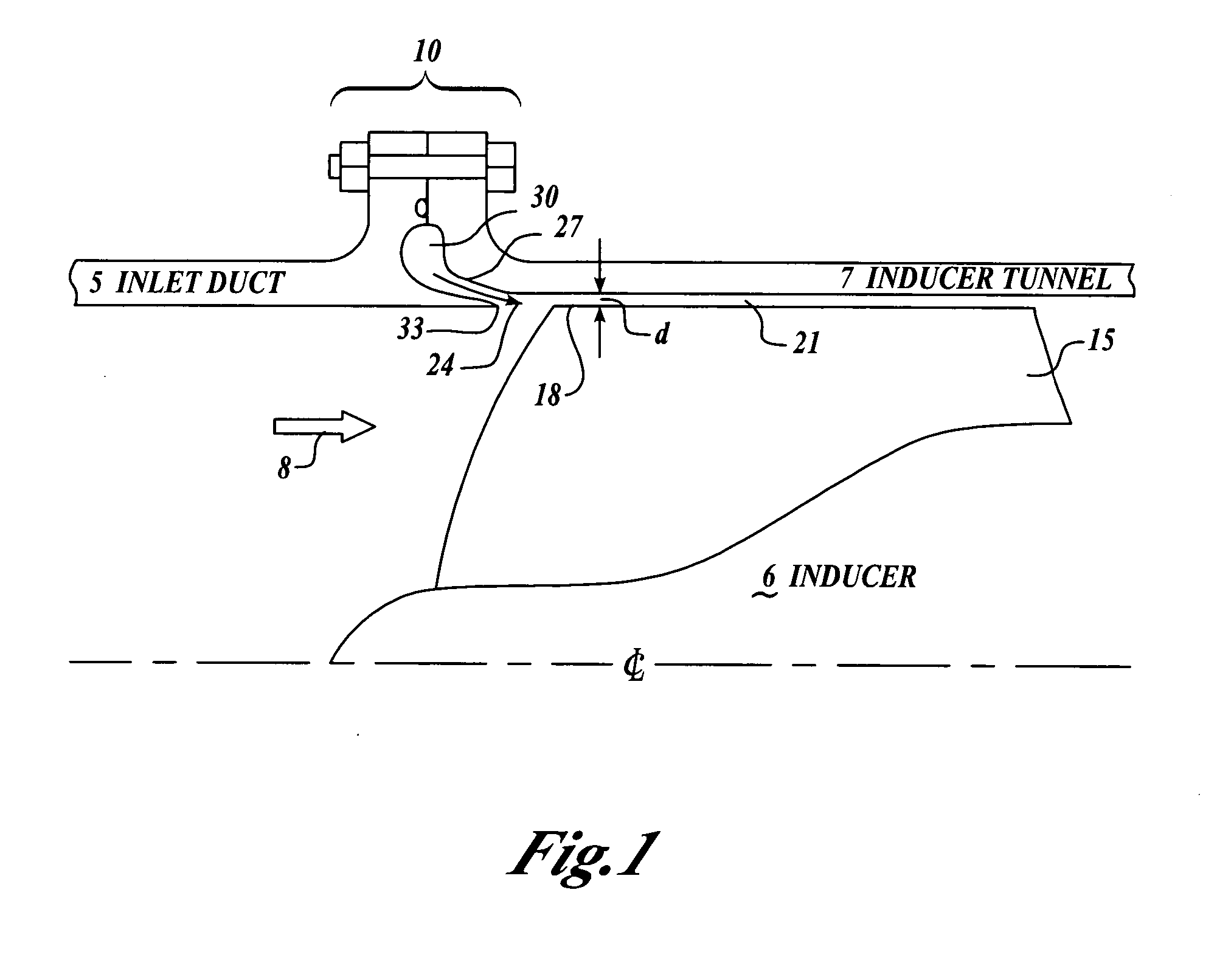
[0019] Referring to FIG. 1, an inlet duct 5 housing an inducer 6 in an induction tunnel housing 7 that includes a vortex suppressor assembly 10. To induce a first fluid flow 8 of fluid through an induction tunnel housing 7, an inducer blade 15 having an inducer blade tip 18 is rotated in the induction tunnel housing 7. The inducer blade 15 rotates in the induction tunnel housing 7 with an inducer tip clea...


PUM


Abstract

Embodiments of the invention provide a method, device, and turbopump configured to suppress higher order cavitations at an inducer tip in a turbopump. An inducer having a tip is rotated, and a first flow is induced axially through the inducer at a first velocity. A second fluid flow is introduced toward a tip of the inducer substantially parallel to the first fluid flow at a second velocity that is greater than the first velocity, such that back flow through the tip of the inducer is reduced.

Description

FIELD OF THE INVENTION [0001] This invention relates generally to fluid motivation and, more specifically, to fluid inducer technology. BACKGROUND OF THE INVENTION [0002] Inducers are typically utilized as the first pumping element of centrifugal and axial flow pumps to lower the inlet pressure at which cavitation results in pump head (discharge pressure) loss. Inducers include blades that are designed to operate in a passage with a small positive incidence angle between the fluid angle relative to a blade pressure side angle as the fluid enters an area between the operating blades know as a blade row. A tip clearance between the blade tip and a wall of the passage is necessary to allow the blade tip to operate within the passage. [0003] Camber is then added to blade geometry after the fluid is captured in the blade row to add work to the fluid raising its tangential velocity and static pressure. The small positive incidence angle near the blade tip is selected based on the gross un...

Claims


Application Information

Patent Timeline
Patent Type & Authority Applications(United States)
IPC IPC(8): F04D29/42F04D29/68
CPCF04D29/426Y10S415/914F04D29/688
Inventor STANGELAND, MAYNARD L.
Owner THE BOEING CO
Why Eureka
Try Eureka