Method f amplifying dna chip signals

a dna chip and signal technology, applied in the field of signal amplification methods for dna chips, can solve the problems of high cost and complicated operations, and achieve the effect of improving the sensitivity of detection of a target gene and simple detection

Inactive Publication Date: 2005-06-16
SANKO JUNYAKU CO LTD
View PDF4 Cites 4 Cited by
  • Summary
  • Abstract
  • Description
  • Claims
  • Application Information

AI Technical Summary

Benefits of technology

[0007] The object of the present invention is to provide a signal amplification method for a DNA chip which can establish efficient signal amplification for a target gene captured on the DNA chip by the PALSAR method and can establish simple detection by contriving design of a pair of HCPs to be used in the PALSAR method.
[0008] In order to solve the above problems, a signal amplification method for a DNA chip according to the present invention improves sensitivity for detection of a target gene on the DNA chip by making use of a self-assembly reaction which forms a double-stranded self-assembly substance having a regular higher-order structure of oligonucleotides.

Problems solved by technology

However, there have been problems that, in comparison with conventionally used Southern blotting (Southern, E. M. Detection of specific sequences among DNA fragments separated by gel electrophoresis.
These methods require, however, complicated operations and a high cost.

Method used


Image

  • Method f amplifying dna chip signals
  • Method f amplifying dna chip signals
  • Method f amplifying dna chip signals

Examples


examples

[0059] The present invention will hereinafter be described in more specific manner by way of the following examples which should be construed as illustrative rather than restrictive.

1. Materials

[0060] The following are oligonucleotide-probes used in the examples:

[1] Probe 1; Capture DNA probe-1a5′-NH2-AAAAAAGCGG GAAATCGTGC GTGACATTAA-3′[2] Probe 2; Target gene-15′-CGTGGCCATC TCTTGCTCGA AGTCCAGGGC GACGTAGCACAGCTTCTCCT TAATGTCACG CACGATTTCC CGCTCGGCCG-3′[3] Probe 3; HCP-15′-CCTGGACTTC GAGCAAGAGA TGGCCGGCAC CACCATGTACCCTGGCATTG GTCCACCGCA AATGCTTCTA GGCGG-3′[4] Probe 4; HCP-25′-GGCCATCTCT TGCTCGAAGT CCAGGCAATG CCAGGGTACATGGTGGTGCC CCGCCTAGAA GCATTTGCGG TGGAC-3′[5] Probe 5; HCP-35′-CCCTGGACTT CGAGCAAGAG CGTGGACATC CGCAAAGACCGCAGGAGTAT GACGAGTCCG-3′[6] Probe 6; HCP-45′-CTCTTGCTCG AAGTCCAGGG GGTCTTTGCG GATGTCCACGCGGACTCGTC ATACTCCTGC-3′[7] Probe 7; Dimer-forming probe-15′-GACTTCGAGC AAGAGATGGC CCTGATAGGG TGCTTGCGAGCCATTGGCAA TGAGCGGTTC-3′[8] Probe 8; Dimer-forming probe-25′-GAGCATCCC...

examples 1 to 3

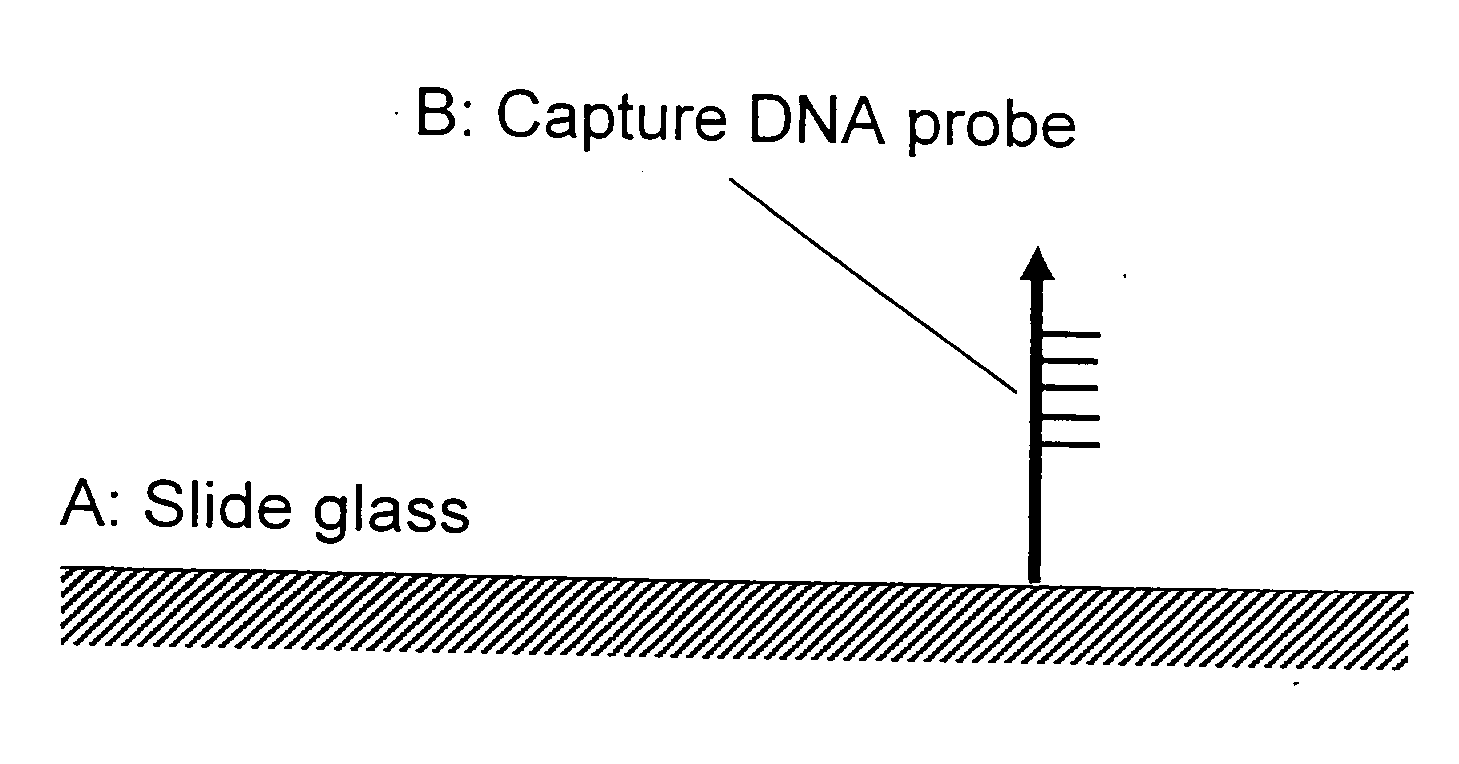
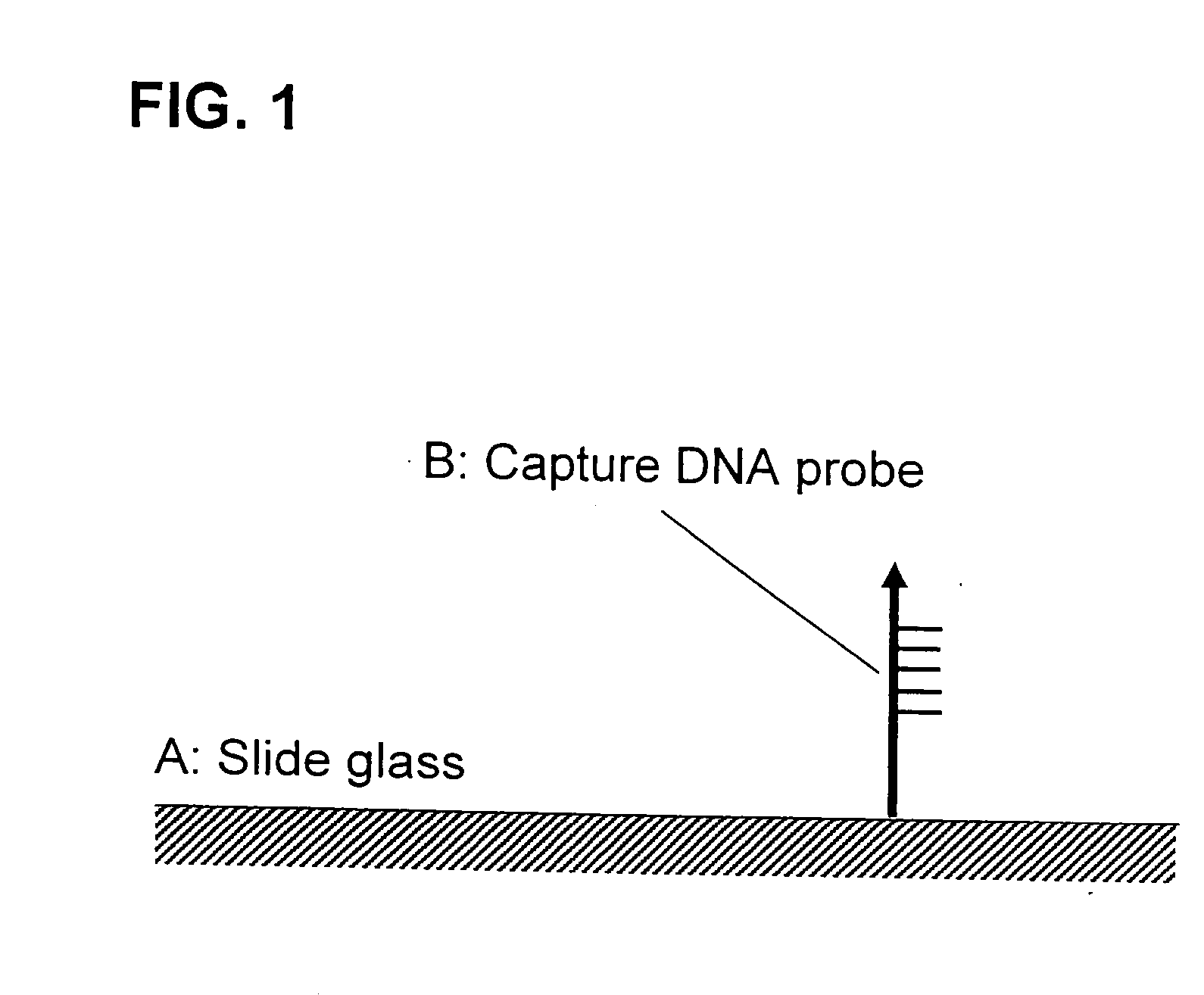
[0063] a) As a capture probe, the capture DNA probe-la having a region complementary to the target gene-i and prepared at 500 ng / μL (Example 1), 50 ng / μL (Example 2), or 5 ng / μL (Example 3) was used, respectively.

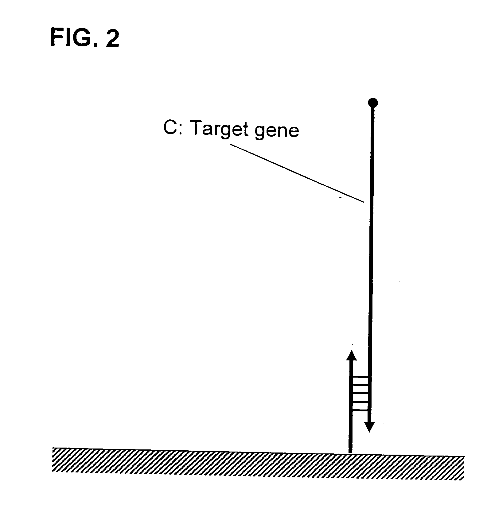
[0064] b) As a primary hybridization solution, 50 ng of the target gene-1 was dissolved in 10 μL of the hybrid solution, followed by heating for 2 minutes at 95° C. to prepare a primary hybridization solution A.

[0065] c) As a secondary hybridization solution, 25 pmoles of Cy3-labeled HCP-1 and 25 pmoles of Cy3-labeled HCP-2 were dissolved in 10 μL of the hybrid solution, followed by heating for 2 minutes at 95° C. to prepare a secondary hybridization solution A.

examples 4 to 6

[0075] a) As a capture probe, the capture DNA probe-1a prepared at 500 ng / μL (Example 4), 50 ng / μL (Example 5), or 5 ng / μL (Example 6) was used, respectively.

[0076] b) As a primary hybridization solution, the above primary hybridization solution A was used.

[0077] c) As a secondary hybridization solution, 25 pmoles of HCP-1 and 25 pmoles of HCP-2 were dissolved in 10 μL of the hybrid solution, followed by heating for 2 minutes at 95° C. to prepare a secondary hybridization solution C.


PUM

PropertyMeasurementUnit
Coloraaaaaaaaaa
Electrical conductoraaaaaaaaaa
Sensitivityaaaaaaaaaa

Abstract

There is provided a signal amplification method for a DNA chip which can establish efficient signal amplification for a target gene captured on the DNA chip by the PALSAR method and can establish a simple detection by contriving design of a pair of HCPs to be used in the PALSAR method. Sensitivity for detection of the target gene on the DNA chip is improved by making use of a self-assembly reaction which forms a double-stranded self-assembly substance having a regular higher-order structure of oligonucleotides.

Description

TECHNICAL FIELD [0001] The present invention relates to a signal amplification method for a DNA chip, and more particularly, relates to a signal amplification method for a gene which can improve sensitivity for detection of a target gene on a DNA chip by making use of a pair of oligonucleotides forming a self-assembly substance, wherein the DNA chip comprises a support or a substrate to bind a gene for capturing the target gene (hereinafter referred to as a support), and the support is of micro plate type, slide glass type, microparticle type, electroconductive substrate type or the like (hereinafter may be generically referred to as a DNA chip). BACKGROUND ART [0002] DNA chips are used for detection of genes in which a number of different DNA probes are densely immobilized on a support of micro plate type, slide glass type, microparticle type, or electroconductive solid substrate type, wherein the support surface is specially processed, followed by hybridization of nucleic acids (t...

Claims


Application Information

Patent Timeline
IPC IPC(8): C12Q1/68
CPCC12Q1/682C12Q2565/113C12Q1/68
Inventor USUI, MITSUGUMITSUKA, MARIHAKII, CHIKAKO
Owner SANKO JUNYAKU CO LTD
Why Eureka
Try Eureka