Lift assist device and method

a technology of lifting assistance and lifting force, which is applied in the field of motion assistance devices, can solve the problems of increased risk of disc prolapse, low back pain, occupation and tasks, etc., and achieve the effects of reducing compressive and shear force, increasing the acceleration of the upper body, and increasing the compressive for

Inactive Publication Date: 2005-06-16
QUEENS UNIV OF KINGSTON
View PDF24 Cites 54 Cited by
  • Summary
  • Abstract
  • Description
  • Claims
  • Application Information

AI Technical Summary

Benefits of technology

[0086] Using the physical constraints of body motion and by estimating the forces acting on different component structures, we can reasonably predict the magnitudes of spinal forces for loads held in various postures. For a better understanding of PLAD's effects on the erector spinae, a first generation model was created in AutoCAD™ 2002 (Autodesk, Inc., San Rafael, Calif.) and the ACIS format was transferred to Visual Nastran 4D®2003 (MSC Software Corp., Santa Ana, Calif.). The elastic members used in PLAD were assumed to be similar to a linear spring constraint in this program. A shaft was attached to the upper body in a manner similar to that of a spine. A revolute motor was applied at the end of the shaft to lift the upper body modelling the erector spinae.
[0087] To find the forces exerted on the erector spinae on the basis of this model, the calculated torque around the revolute motor (MA in FIG. 4) was found. As seen in equation 15, dividing the torque or moment around the z-axis, by the distance between the spine and erector spinae, “d”, gives the amount of force (Fm) exerted by this muscle.
[0088] There are some differences between the calculated results and the results found by modelling, for example, in terms of curve shape and magnitude. The model lifts the load dynamically (20 degrees/sec), therefore it calculates the effect of the upper body and load acceleration on the produced model. Thus it shows higher values at the beginning and smaller values at the end of the lift, perhaps because the lever arm gets shorter.
[0089] Compressive and shear forces exerted on the L4/L5 disc were found by modelling the forces along the shaft of the model and the erector spinae, with results show in FIGS. 11 and 12. These mo...

Problems solved by technology

Occupations and tasks which demand frequent and heavy lifting are associated with a greatly increased risk of disc prolapses (Kelsey et al., 1984) and with low back pain in general (Kelsey and White, 1980).
However, when loads are within perceived human lifting capability, there is a tendency for subjects to lift manually as most mechanical lifting aids are slower than human speed and may not be easily accessible (Kazerooni, 2002).
Current research findings su...

Method used


Image

  • Lift assist device and method
  • Lift assist device and method
  • Lift assist device and method

Examples


example 1

Development of Static Equations for Lifts

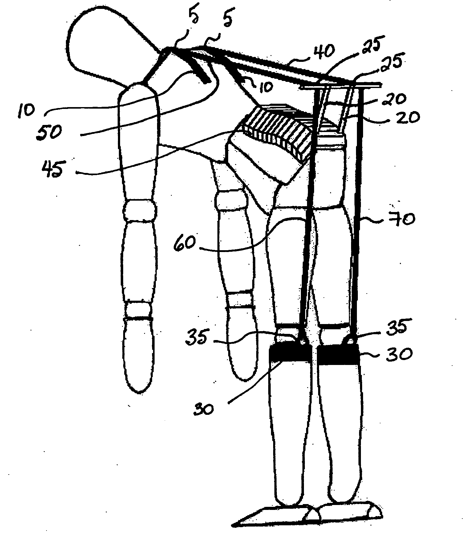
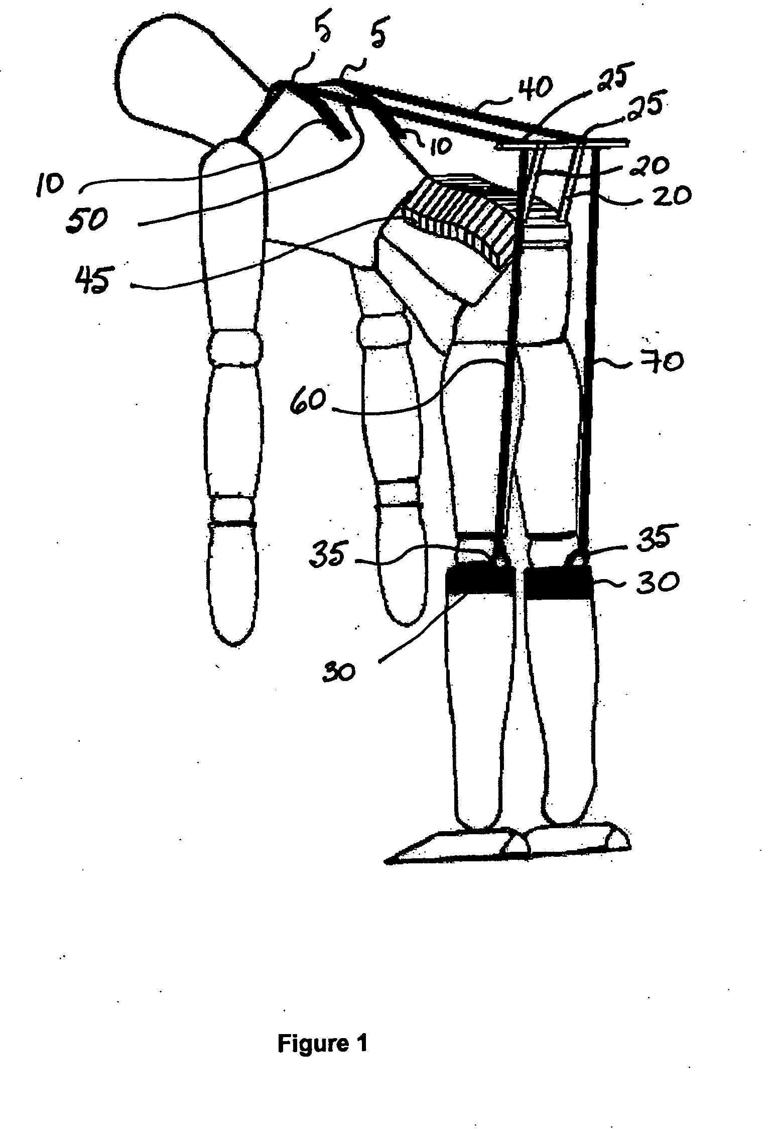
[0071] A simple two-dimensional model was developed to predict how the erector spinae muscle activity is affected by the personal lift assist device of the preferred embodiment of the invention (shown in FIG. 1). This model can be explained arithmetically through a moment arm analysis of the forces generated during lifting without PLAD (as shown in FIG. 3) and with PLAD (as shown in FIG. 4). The development of static balance equations improves our understanding of forces that act about a point A in the spinal column, typically at the L4 / L5 disc or the L5 / S1 disc of the spinal column.

example 1a

Development of Static Equations for Lifts Without PLAD

[0072] If we assume the weight of a subject's upper body is “W ,” and the weight of the object to be lifted is “W2”, then the vertical force exerted to lift a load, “W”, can be found using equation 1.

W=W1+W2   (1)

[0073] The distance, “b”, between the center of gravity of “W” and the L4 / L5 disc of the spinal column is found by equation 2, wherein “b1” is the distance between the center of gravity of the subject's upper body and the L4 / L5 disc, and “b2” is the distance between the center of gravity of the object to be lifted and the L4 / L5 disc (see FIG. 3).

b=(b1W1+b2W2) / W   (2)

[0074] The distance between the erector spinae and the lumbar vertebrae, or the “effective lever arm”, is denoted as “d”. An equilibrium equation can be obtained for the sum of the moments at a point A, denoted “MA” where the force exerted by the erector spinae muscle is denoted as “Fm”.

ΣMA=0=Fmd−Wb   (3)

The force exerted on the erector spinae muscle,...

example 1b

Development of Static Equations for Lifts with PLAD

[0076] We may quantify the affects of wearing the PLAD embodiment of the invention pictured in FIG. 1 by adding it to the relevant equations. FIG. 4 depicts the parameters involved with a subject wearing such a device. The force exerted by the erector spinae muscle, “Fm”, in this condition can be calculated with equation 10 where the force exerted by the device is represented as “FPLAD” and the distance between the anchor of the lower back and the L4 / L5 disc, or moment arm of the device, is denoted as “a”.

Fmd+FPLADa−Wb=ΣMA=0   (9)

Fm=(Wb−FPLADa) / d   (10)

[0077] Comparing equations 4 and 10 shows that the amount of force exerted by the erector spinae when a subject is wearing PLAD and bending from the waist to lift an object from the floor, is an amount [FPLADa / d] less than the same situation without PLAD, where the distance between the erector spinae and lumbar vertebrae, “d”, is constant.

[0078] The compressive force acting on th...


PUM


Abstract

The invention relates to a device and method for assisting a subject to perform a motion such as a lift. The invention comprises a first anchor attachable to a first side of a joint of the subject's body, a second anchor attachable to a second side of the joint; and an elastic member connecting the first anchor and the second anchor, such that articulation of the joint in a first direction causes deformation of the elastic member and storing of energy, and articulation of the joint in a second direction causes relaxation of the elastic member wherein the energy is released and assists the subject to perform a motion in said second direction. The invention may be used at a subject's waist, ankle, wrist, knee, hip, elbow, shoulder, and/or at least one joint of the back and/or neck.

Description

RELATED APPLICATIONS [0001] This application claims the benefit of the filing date of U.S. Provisional Patent Application No. 60 / 529,111, filed Dec. 15, 2003, the contents of which are incorporated herein by reference in their entirety.FIELD OF THE INVENTION [0002] The invention relates to a motion assistance device that is worn by a subject, and which stores and provides energy for aiding a task or motion involving articulation of one or more joints, particularly lifting or moving a mass. In particular, the invention provides a device and method for assisting a subject to perform a manual task such as lifting an object. BACKGROUND OF THE INVENTION [0003] During bending and lifting activities, erector spinae muscles must generate a large extensor moment to raise the upper body, and the object lifted, into an upright position (McGill and Norman, 1986). Since these muscles act on short lever arms, a high tensile force is required, and the lumbar intervertebral discs are subjected to a...

Claims


Application Information

Patent Timeline
IPC IPC(8): A61F5/02A63B21/00A63B21/02A63B23/02F16D65/14
CPCA61F5/026A61H2201/1642A61H2201/165A63B21/00181A63B21/02A63B21/072A63B23/0211A63B23/0233A61H1/024A61H1/0244A61H1/0266A61H3/00A61H2201/1215A61H2201/1616A61H2201/1623A61H2201/163A61H3/008
Inventor ABDOLI-ERAMAKI, MOHAMMAD
Owner QUEENS UNIV OF KINGSTON
Why Eureka
Try Eureka