Methods and devices for spinal fixation element placement

a technology of spinal fixation and element placement, which is applied in the field of spinal fixation element placement methods and devices, can solve the problems of increasing patient trauma and recovery time, significant damage to surrounding tissue and muscle, and undesired lengthening of surgical procedures

Active Publication Date: 2005-06-16
DEPUY SYNTHES PROD INC
View PDF99 Cites 383 Cited by
  • Summary
  • Abstract
  • Description
  • Claims
  • Application Information

AI Technical Summary

Benefits of technology

[0007] In an exemplary embodiment, each percutaneous access device includes first and second opposed sidewall openings, and at least one of the first and second sidewall openings extends from the distal end and terminates at a position distal to the proximal end. The percutaneous access devices can also optionally include a cannula, sleeve, or similar device disposed therearound that is effective to prevent removal of each percutaneous device from the spinal anchor coupled thereto. The sleeve preferably includes at least one sidewall opening formed therein that is adapted to align with the at least one sidewall opening in the percutaneous access device.
[0008] In another embodiment of the present invention, a percutaneous access system for introducing a spinal fixation element into a patient's body is provided. The system includes at least two spinal anchors that are adapted to be disposed in bone, at least one elongate, generally cylindrical hollow tube having at least one sidewall opening extending from the distal end thereof and terminating at a position distal to the proximal end, and a spinal fixation element. The system can also include at least one sleeve which is adapted to be slidably disposed around at least a portion of one of the hollow tubes. The sleeve(s) preferably includes at least one sidewall opening formed therein that is adapted to align with the sidewall opening(s) formed in the hollow tube. The system can also include a driver mechanism having a proximal handle portion, and a distal end that is adapted to couple to a spinal anchor such that rotation of the driver mechanism is effective to thread the spinal anchor into bone. The driver mechanism is preferably adapted to be disposed through the hollow tube(s).

Problems solved by technology

While this procedure offers advantages over prior art invasive techniques, the transverse introduction of the rod can cause significant damage to surrounding tissue and muscle.
Moreover, the use of three separate access sites can undesirably lengthen the surgical procedure, and increase patient trauma and recovery time.

Method used


Image

  • Methods and devices for spinal fixation element placement
  • Methods and devices for spinal fixation element placement
  • Methods and devices for spinal fixation element placement

Examples


Embodiment Construction

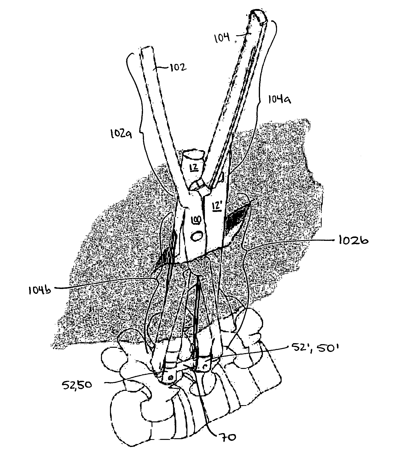
[0023] The present invention provides minimally invasive methods and devices for introducing a spinal fixation element into a surgical site in a patient's spinal column. In general, the method involves positioning a spinal fixation element through openings formed in at least two adjacent percutaneous access devices such that the spinal fixation element extends between the at least two adjacent percutaneous access devices in a lengthwise orientation. The spinal fixation element can then be advanced in a distal direction to seat the spinal fixation element in the receiver heads of the adjacent spinal anchors, or to otherwise position the spinal fixation element in relation to the adjacent spinal anchors. A fastening element or other closure mechanism can optionally be applied to each spinal anchor to engage the spinal fixation element within the receiver heads of the adjacent anchors, or to otherwise directly or indirectly connect the spinal fixation element to the anchors.

[0024] Whi...


PUM


Abstract

Minimally invasive methods and devices are provided for positioning a spinal fixation element in relation to adjacent spinal anchors. In an exemplary embodiment, the device is a percutaneous access device that can be coupled to a spinal anchor, and the method includes the step of positioning a spinal fixation element through at least one sidewall opening of at least two percutaneous access devices such that the spinal fixation element extends in a lengthwise orientation that is substantially transverse to the longitudinal axis of each percutaneous access device. The spinal fixation element can then be advanced in the lengthwise orientation to seat the spinal fixation element in or adjacent to the receiver heads of at least two adjacent spinal anchors. A fastening element or other closure mechanism can then be applied to each spinal anchor to engage the spinal fixation element within the receiver heads of the adjacent anchors.

Description

FIELD OF THE INVENTION [0001] This application relates to tools for use in spinal surgery, and in particular to minimally invasive methods and devices for introducing a spinal fixation element to one or more spinal anchor sites within a patient's spine. BACKGROUND OF THE INVENTION [0002] For a number of known reasons, spinal fixation devices are used in orthopedic surgery to align and / or fix a desired relationship between adjacent vertebral bodies. Such devices typically include a spinal fixation element, such as a relatively rigid fixation rod, that is coupled to adjacent vertebrae by attaching the element to various anchoring devices, such as hooks, bolts, wires, or screws. The fixation elements can have a predetermined contour that has been designed according to the properties of the target implantation site, and once installed, the instrument holds the vertebrae in a desired spatial relationship, either until desired healing or spinal fusion has taken place, or for some longer p...

Claims


Application Information

Patent Timeline
Patent Type & Authority Applications(United States)
IPC IPC(8): A61B17/88A61F2/44
CPCA61B17/7079A61B17/7082A61B17/7002A61B17/7091A61B17/7085
Inventor ANDERSON, DAVID GREGROSS, GEORGE JOSEPH
Owner DEPUY SYNTHES PROD INC
Why Eureka
Try Eureka