System for measuring points on a vehicle during damage repair

a technology for measuring points and vehicles, applied in the direction of distance measurement, instruments, digital computer details, etc., can solve the problems of prior art system failure, inability to achieve widespread use and industry approval, and inability to meet the needs of vehicles

Active Publication Date: 2005-06-16
MATRIX ELECTRONICS MEASURING PROPERTIES
View PDF35 Cites 23 Cited by
  • Summary
  • Abstract
  • Description
  • Claims
  • Application Information

AI Technical Summary

Benefits of technology

[0014] The system for measuring points on a vehicle during damage repair utilizes encoder motors, sometimes called servos, which rotate a drive shaft in fine, measurable increments, such as 2,000 increments per revolution, to rotate at least two cameras fixed in a single plane and along the same line until they are centered on a target that includes concentric rings of light and dark circular patterns and calculates the location of the point through well-know standard triangulation techniques based on the law of sines using custom computer software. The at least two cameras are spaced from one another by an equal fixed amount along a spacer bar. The spacer bar may be mounted for precisely measured movement along a particular axis.

Problems solved by technology

When motor vehicles are damaged in collisions or wrecks, the structures of the vehicle, particularly those providing structural integrity to the vehicle, are often bent or otherwise deformed.
All of these prior art systems have failings that inhibit their widespread use and industry approval.
This system allows for errors in setting up the rulers and in reading the measurements and is very time consuming and laborious.
The ambient noise in vehicle repair shops interferers with any type of acoustic signals.
This system is inadequate for present purposes because in vehicle repair, the reference points are given by the manufacturer or others and cannot be selected by the user.
Further these reference points are principally underneath the vehicle and cannot be conveniently illuminated or otherwise located from a single fixed source.

Method used


Image

  • System for measuring points on a vehicle during damage repair
  • System for measuring points on a vehicle during damage repair
  • System for measuring points on a vehicle during damage repair

Examples


Embodiment Construction

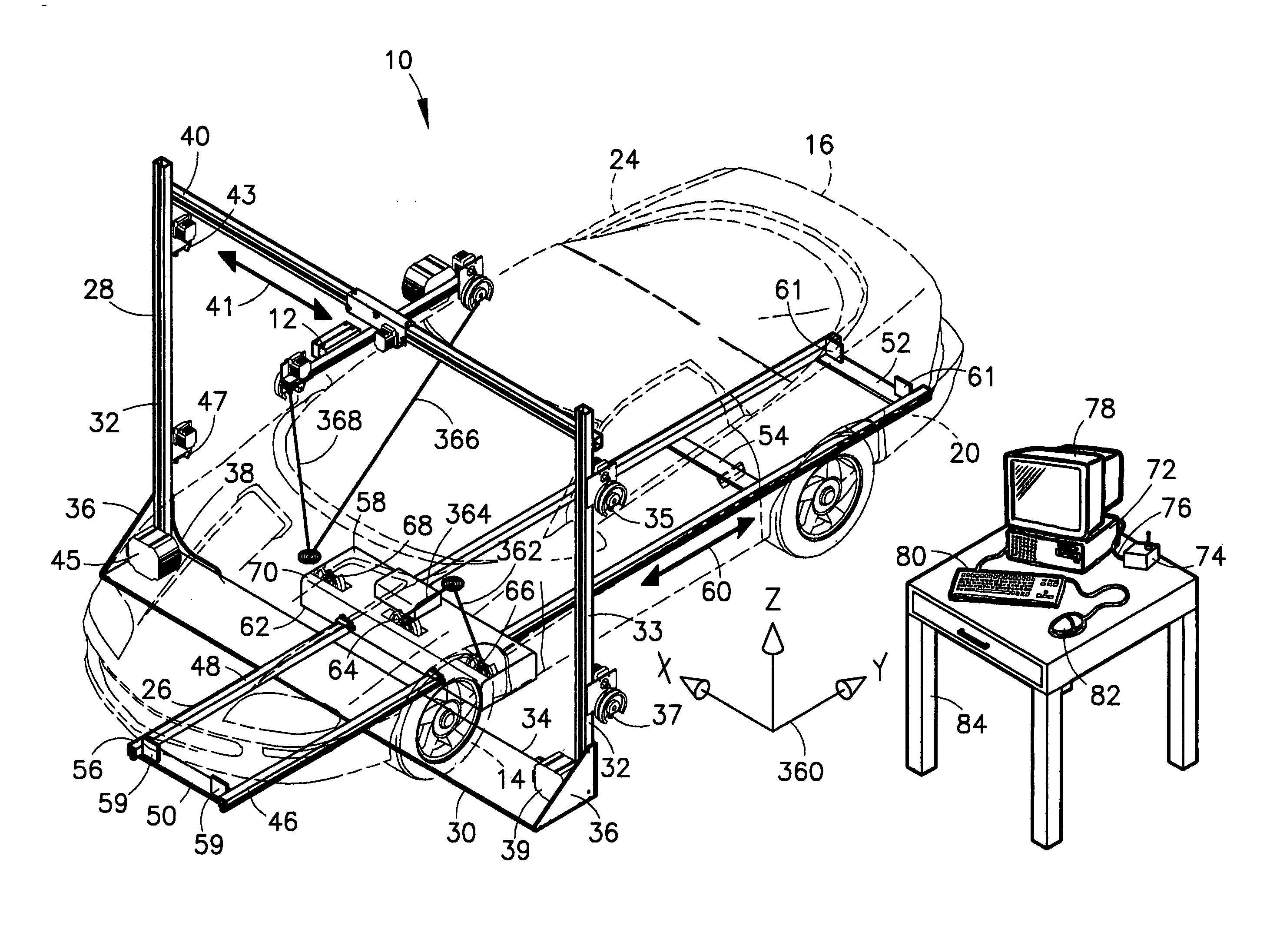
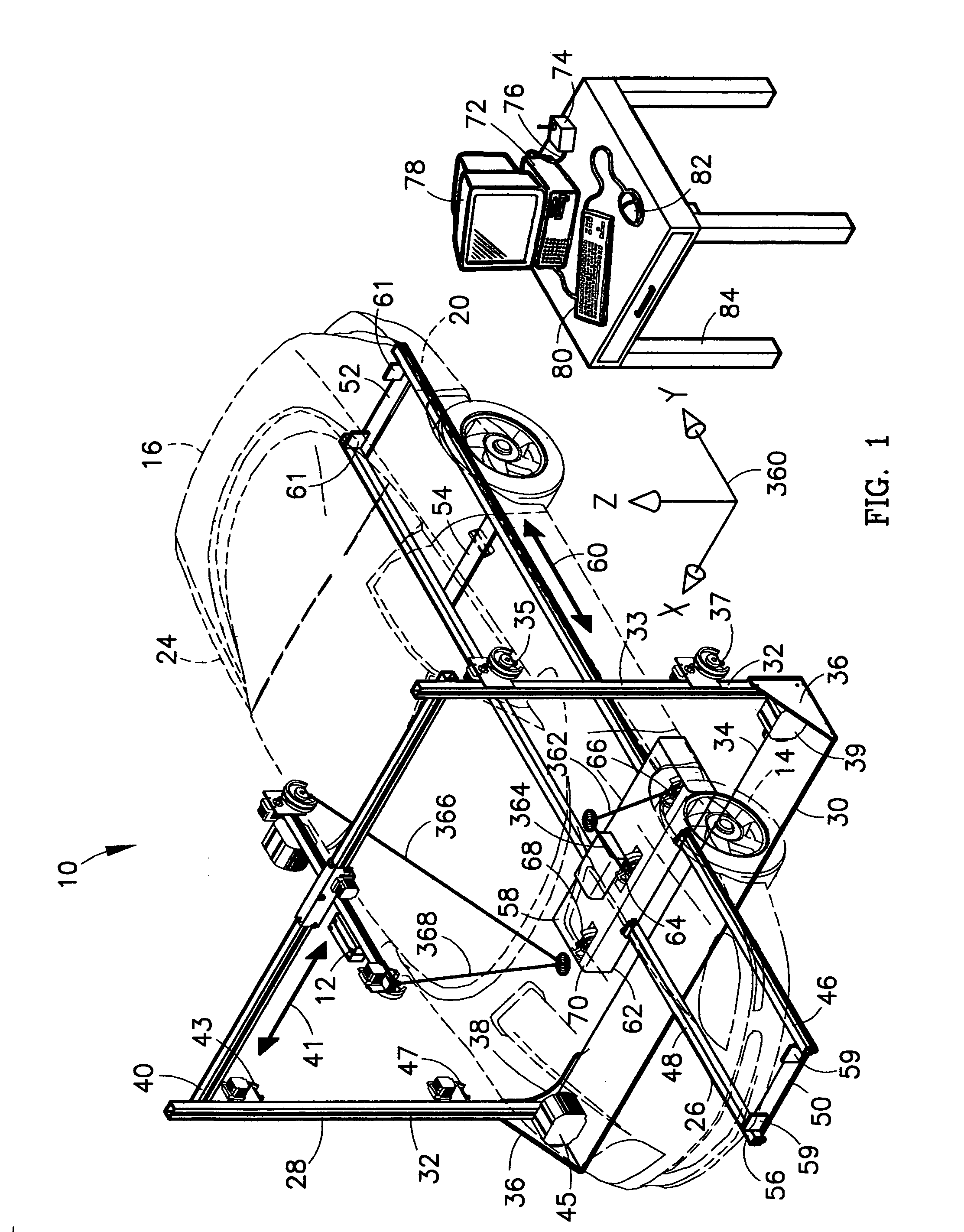
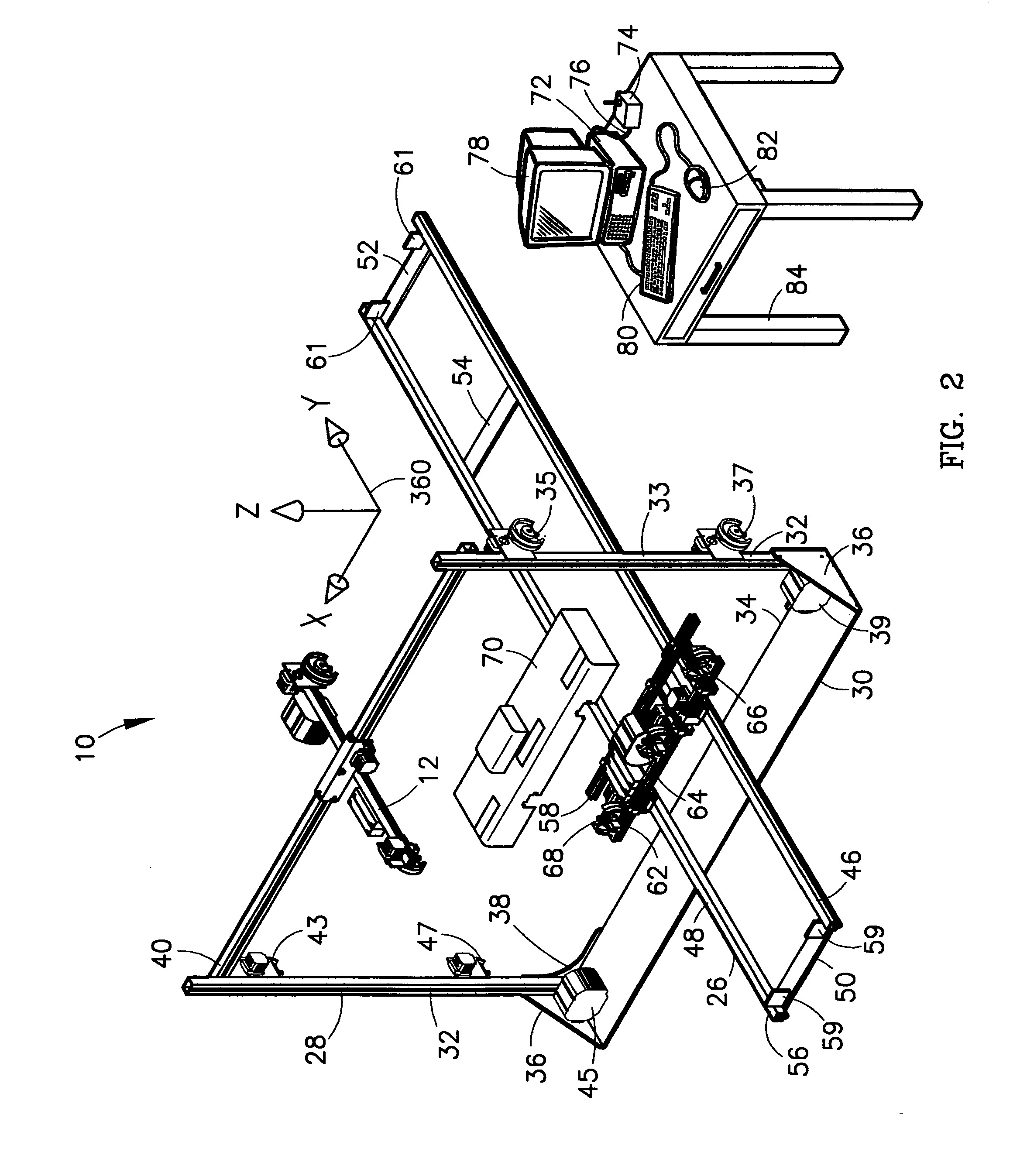
[0051] Referring to FIG. 1, the system for measuring points on a vehicle during damage repair, or vehicle measuring system 10, includes four different assemblies for measuring points on a vehicle, thereby providing measurement data for nearly the entire vehicle without having to rearrange or move a particular data collection system. A front-end measuring unit 12 is placed approximately in the proximity of the front wheels 14 of the vehicle 16, with the upright frame 28 being perpendicular to the longitudinal centerline of the vehicle 16. The driver's side 20 of the vehicle 16 is defined as the side of the vehicle 16 that is closest to the driver when he is in the driver's seat and the passenger's side 24 is defined as the side of the vehicle 16 that is closest to a passenger in the passenger's seat adjacent to the right-hand side of the vehicle 16 as referenced from the driving position in the car. The second measuring unit is an undercarriage measuring unit 26, which lies flat on t...


PUM


Abstract

A carriage moves back and forth under a vehicle and three cameras or laser fixed along one axis pivot in a common plane, utilizing two cameras at time to locate a target fixed to a reference point on the undercarriage of the vehicle. Triangulation calculations, combined with the location of the cameras provide the location of the reference point in space in a three-dimensional coordinate system and compare that location with a stored designed location of the reference point prior to the crash, allowing the vehicle structure to be returned to its designed shape by other equipment.

Description

CROSS-REFERENCE TO RELATED APPLICATIONS [0001] This application is a continuation-in-part of a regular United States Patent Application of the same title filed on Oct. 27, 2004, application Ser. No. 10 / 974,288, which claims priority under 35 U.S.C. §119 (e)(1) from U.S. Provisional Patent Application, application No. 60 / 527,464, filed Dec. 4, 2003. The attached text and drawings includes the exact material filed on Oct. 27, 2004, with new matter added. The inventors are identical in the earlier filed provisional patent application, the regular patent application claiming priority from the provisional patent application and the present continuation-in-part application.STATEMENT REGARDING FEDERALLY SPONSORED RESEARCH OR DEVELOPMENT. [0002] Not applicable. BACKGROUND OF THE INVENTION [0003] The present invention is related to an apparatus and process for determining the location of a point in space and measuring the deviation of that location from a desired position. More particularly,...

Claims


Application Information

Patent Timeline
Patent Type & Authority Applications(United States)
IPC IPC(8): G01B5/00G06F7/00G06F19/00
CPCG01B5/0025
Inventor SRACK, ROBERT W.DAY, DWIGHT
Owner MATRIX ELECTRONICS MEASURING PROPERTIES
Why Eureka
Try Eureka