Variable turbine cooling flow system

a technology of variable turbines and cooling flow, which is applied in the direction of valve operating means/releasing devices, machines/engines, transportation and packaging, etc., can solve the problems of component fatigue, adversely affecting engine performance, and increasing engine nois

Inactive Publication Date: 2005-06-23
HONEYWELL INT INC
View PDF11 Cites 12 Cited by
  • Summary
  • Abstract
  • Description
  • Claims
  • Application Information

AI Technical Summary

Benefits of technology

[0011] In still a further aspect of the present invention, a method for modulating cooling flow to a turbine, comprises providing the cooling flow along a flow path; disposing a flow restriction element in the flow path having at least two sets of orifices therein; connecting an interior of a bellows with either a source of pressurized air or with ambient air; defining the interior of the bellows by a bellows housin...

Problems solved by technology

Use of an excess of this air, because it has had compression work done on it by the engine, adversely impacts the engine performance.
The radial cooling over the leaf spring end 152 may also result in “reeding” and increased noise in the engine.
This could result in component fatigue and c...

Method used


Image

  • Variable turbine cooling flow system
  • Variable turbine cooling flow system
  • Variable turbine cooling flow system

Examples


Embodiment Construction

[0016] The following detailed description is of the best currently contemplated modes of carrying out the invention. The description is not to be taken in a limiting sense, but is made merely for the purpose of illustrating the general principles of the invention, since the scope of the invention is best defined by the appended claims.

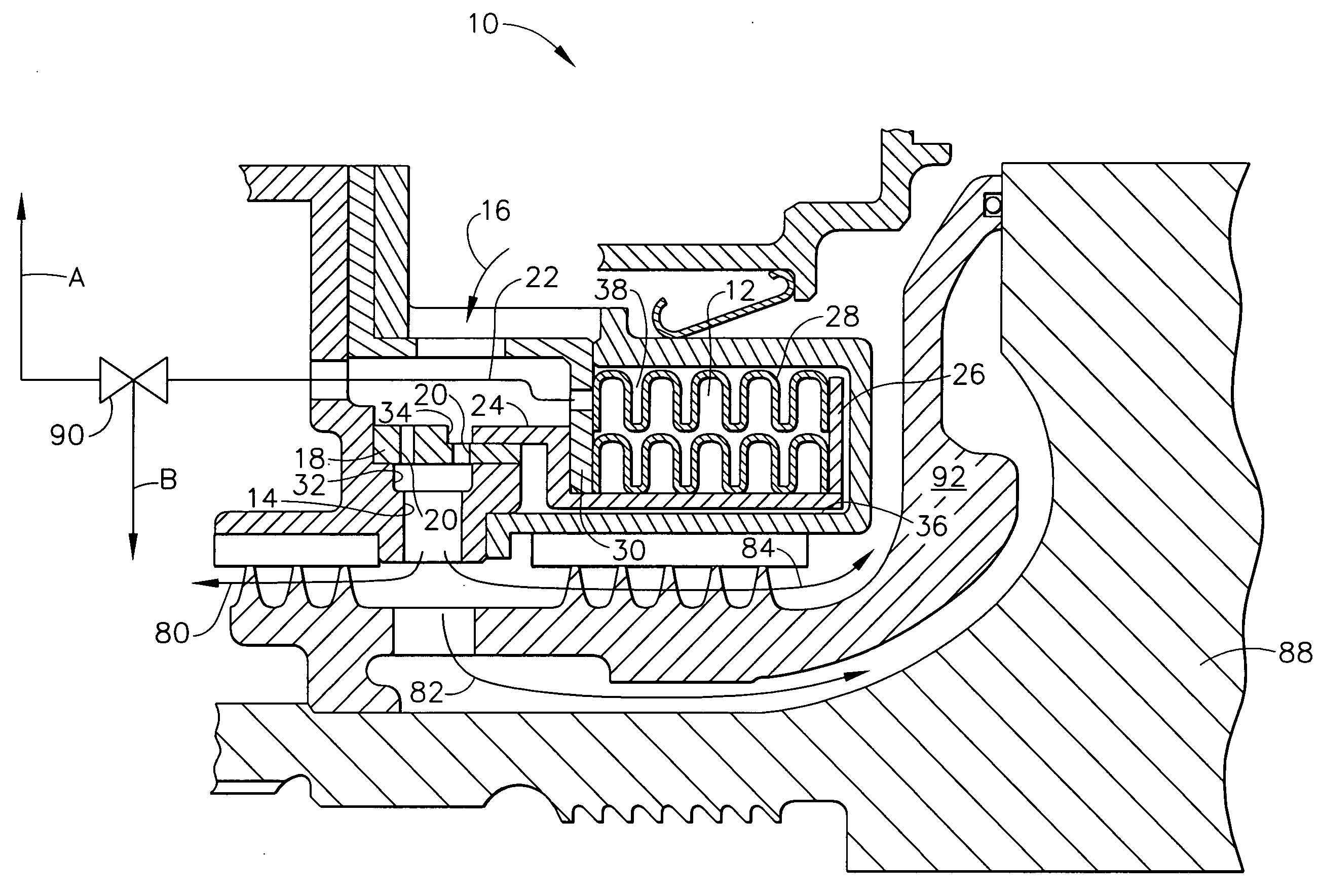
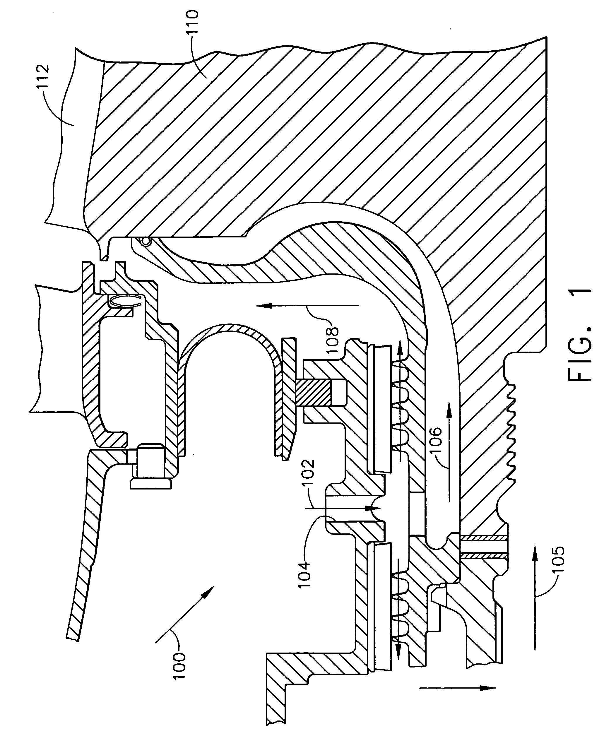
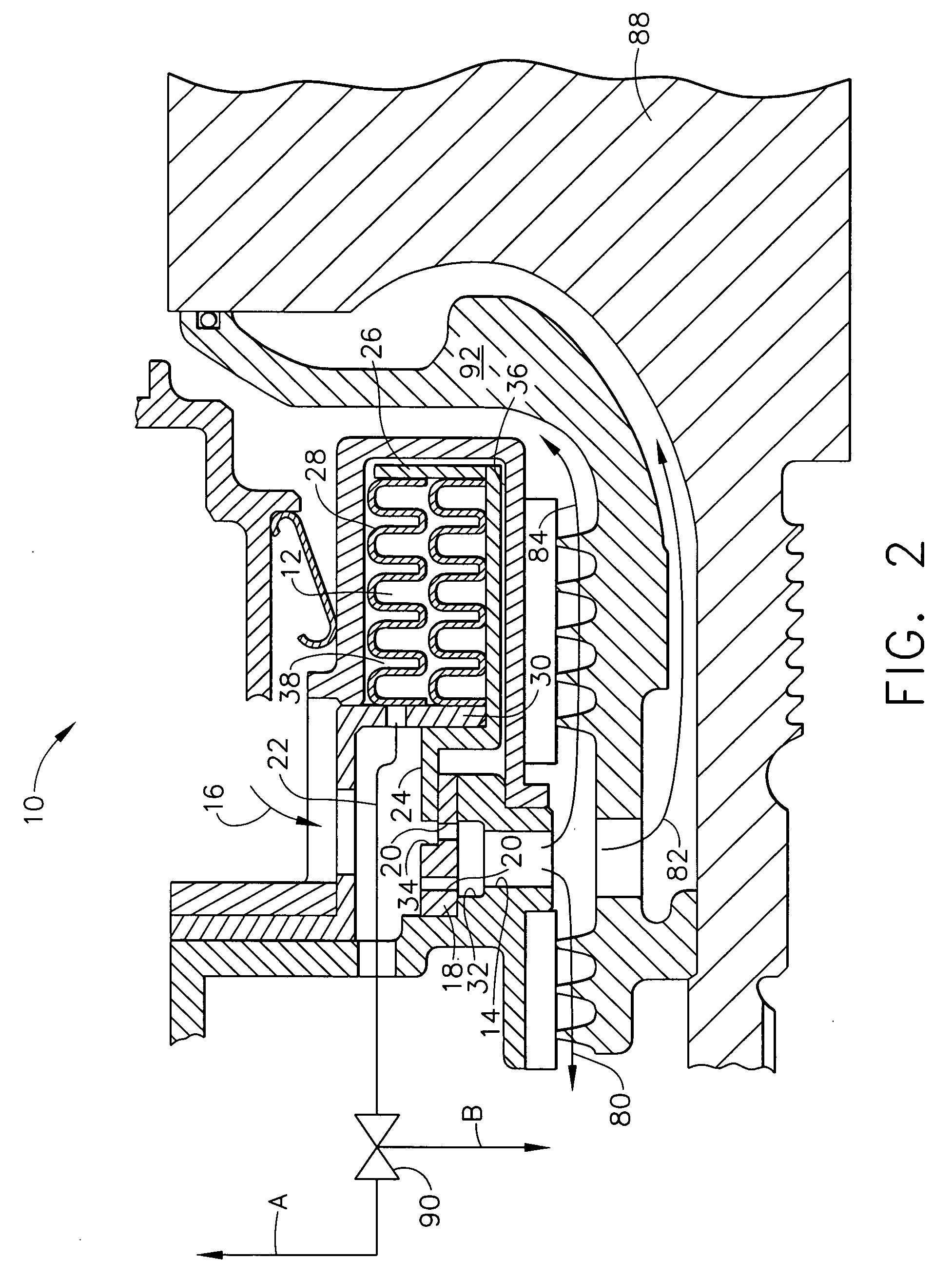
[0017] The present invention provides a turbine rotor (disk, blades and sealplate) cooling system that provides a variable flow of cooling air dependent upon engine conditions such as turbine gas temperature or power level angle. The cooling system of the present invention reduces the amount of coolant flow being delivered to the turbine blades and disk at low power conditions. As discussed in greater detail below, the present invention provides a cooling system that is simple to manufacture, overcomes the effects of varying altitudes, and gives a failure mode cooling sufficient to prevent engine damage. Moreover, another benefit of the cooling system...


PUM


Abstract

Cooling air to the blades and disks of a gas turbine may be modulated to provide a variable turbine cooling flow. A bellows may be extended by providing a high pressure compressor discharge flow to an interior of the bellows. The bellows may be compressed when the interior of the bellows communicates with ambient pressure air. The extension/compression of the bellows moves an arm over orifices in a cooling air flow path. The pressure inside of the bellows is metered to move the arm over at least one orifice, thereby restricting cooling air flow when the engine is running at low power. The pressure inside of the bellows is metered to move the arm to uncover all of the slots to provide maximum cooling flow when the engine is running at high power. The resulting variable cooling flow system results in less need for cooling air at low powers, thus reducing engine fuel consumption.

Description

BACKGROUND OF THE INVENTION [0001] The present invention generally relates to a system for providing cooling flow to the turbine components of a gas turbine and, more particularly, to a system for providing a variable turbine cooling flow to the turbine at various power and altitude conditions. [0002] A conventional turbine rotor cooling system may be designed to satisfy cooling needs of the high pressure turbine (HPT) blade and of the turbine disk at maximum turbine inlet temperature and compressor discharge conditions. This condition usually occurs at maximum engine power. At lower power settings, the turbine coolant air and gaspath temperatures are much lower. Coolant air temperature is lower at altitude than at sea level, even when gaspath temperature is high. In these cases, since the cooling circuit geometry is fixed the coolant flow rate requirements are less than the actual flow rate. The source of the cooling air is compressor discharge air. Use of an excess of this air, be...

Claims


Application Information

Patent Timeline
IPC IPC(8): F01D17/14F02C7/18F02C9/20
CPCF01D17/141F02C7/18F05D2250/61F05D2240/55F05D2240/57F02C9/20Y10T137/7781
Inventor MORGAN, PETER L.HOWE, WILLIAM J.MORRIS, MARK C.ALLAN, ADRIAN R.PALMER, DONALD L.
Owner HONEYWELL INT INC
Why Eureka
Try Eureka