
Conveyor oven with energy saving baffle mechanism and method

a technology of baffle mechanism and conveyor oven, which is applied in the direction of oven doors/gates, baking ovens, food preparation, etc., can solve the problems that loss of heat can seriously affect the thermal efficiency of the oven, and achieve the effect of reducing heat loss from the oven cavity through the opening

Inactive Publication Date: 2005-06-23
LINCOLN FOODSERVICE PRODS
View PDF9 Cites 40 Cited by
  • Summary
  • Abstract
  • Description
  • Claims
  • Application Information

AI Technical Summary

Benefits of technology

[0005] A conveyor oven of the present invention comprises an oven cavity that has at least one opening. A conveyor is positioned to extend into the oven cavity via the opening. A source of thermal energy provides heat in the oven cavity. A baffle is located within the opening and is operable between a closed position and an open position. The heat loss from the oven cavity via the opening is reduced when the baffle is in the closed position versus when the baffle is in the open position.
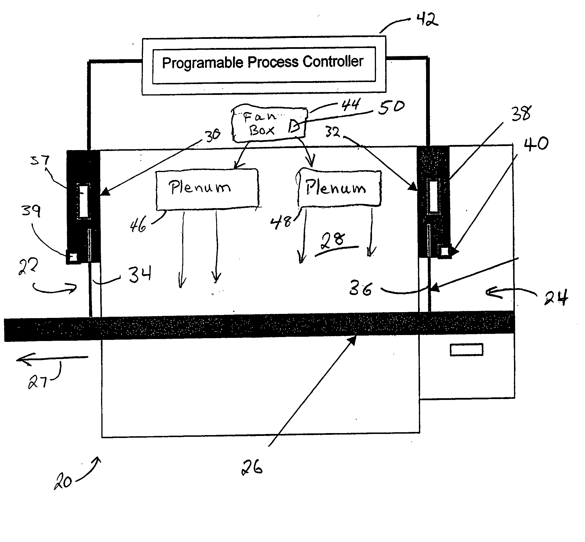
[0008] Preferably, a controller controls the baffle to be in the closed position except for a time required for a passage of a food product carried by the conveyor through the opening, thereby minimizing the heat loss. The baffle further comprises a module that comprises a drive unit that controls the movement of the baffle between an open position and a closed position. The controller controls the baffle to be in the open and closed positions based on a position of the food product relative to the opening, a speed of the conveyor and a predetermined length of the oven cavity.
[0012] A method of the present invention controls a conveyor oven that comprises an oven cavity that includes at least one opening and a conveyor that extends through the opening. The method comprises providing thermal energy in the oven cavity and, during a cooking operation, covering the opening with a baffle when a food product is disposed within the cavity. The heat loss from the oven cavity via the opening is reduced when the baffle is in a closed position versus when the baffle is in an open position.

Problems solved by technology

The lost heat can seriously affect the thermal efficiency of the oven.

Method used

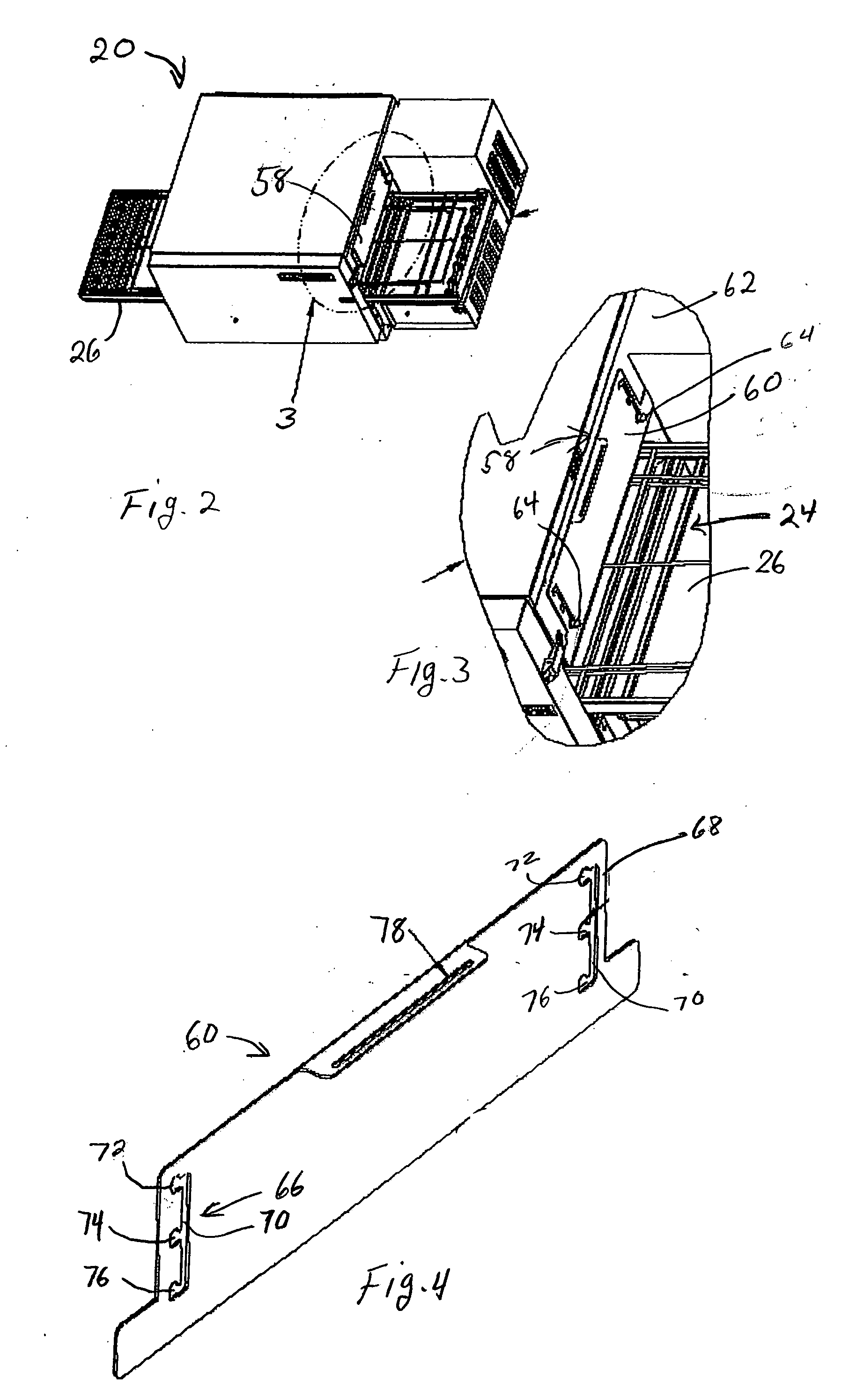

Image

  • Conveyor oven with energy saving baffle mechanism and method
  • Conveyor oven with energy saving baffle mechanism and method
  • Conveyor oven with energy saving baffle mechanism and method

Examples


Embodiment Construction

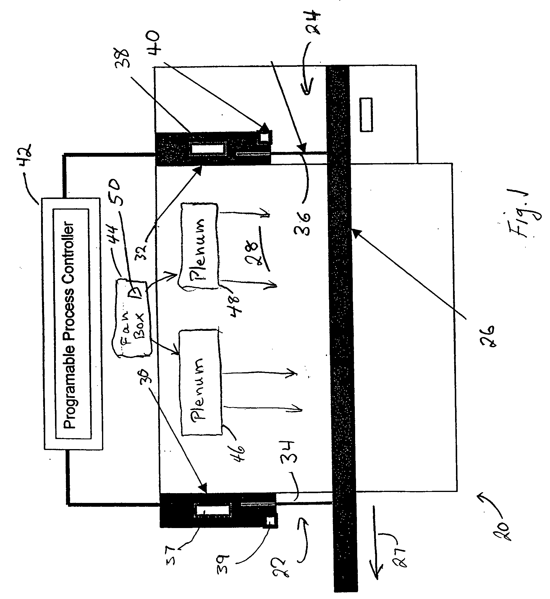
[0024] Referring to FIG. 1, a conveyor oven 20 of the present invention comprises an oven cavity 28 with an outlet 22 and an inlet 24. A conveyor 26 is positioned to convey food products in the direction shown by an arrow 27, the food products entering oven cavity 28 via inlet 24 and leaving via outlet 22. A module 32 and a module 30 are located adjacent inlet 24 and outlet 22, respectively. In the embodiment shown in FIG. 1, modules 30 and 32 are mounted above conveyor 26. A baffle 34 and a baffle 36 are mechanically coupled to modules 30 and 32, respectively. A controller 42 is electrically coupled to modules 30 and 32. Baffle 34 and module 30 comprise a baffle mechanism and baffle 36 and module 32 comprise a baffle mechanism.

[0025] Module 30 includes a drive unit shown as a solenoid valve 37 and a proximity sensor 39. Module 32 includes a drive unit shown as a solenoid valve 38 and a proximity sensor 40. Controller 42 responds to signals from proximity sensors 39 and 40 to contr...


PUM


Abstract

A conveyor oven with improved energy efficiency. The energy efficiency is achieved by providing baffles at an inlet and an outlet of the conveyor oven. The baffles are individually controlled to be closed during cooking operations except for the time required for the passage of a food product through the respective inlet and outlet. The baffles can be operated manually or by electrically driven devices such as solenoids or electric motors. A controller can be used to control the open and closed times of the baffles based on sensor inputs as well as the speed of the conveyor, a predetermined length of the oven cavity between the inlet and outlet and a size of the food product.

Description

RELATED APPLICATIONS [0001] This application claims the benefit of U.S. Provisional Patent Application No. 60 / 523,199, filed on Nov. 18, 2003, and of U.S. Provisional Patent Application No. 60 / 612,718, filed on Sep. 24, 2004, the entire contents of both of which are hereby incorporated by reference.FIELD OF THE INVENTION [0002] The present invention relates to a conveyor oven with an energy saving baffle mechanism and method. DISCUSSION OF THE BACKGROUND ART [0003] Conveyor ovens typically transport food on a conveyor along a cooking path between an inlet and an outlet. Heat provided along the cooking path can escape the oven through the inlet and the outlet. The lost heat can seriously affect the thermal efficiency of the oven. [0004] Thus, there is a need to reduce the heat loss in a conveyor oven. SUMMARY OF THE INVENTION [0005] A conveyor oven of the present invention comprises an oven cavity that has at least one opening. A conveyor is positioned to extend into the oven cavity ...

Claims


Application Information

Patent Timeline
IPC IPC(8): A21BA21B1/48A23L1/00A23L3/18A23L5/10
CPCA21B1/48A21B3/02A23L3/18A23L1/0135Y02P60/85A23L5/17
Inventor HUANG, MING LUNGMILZ, STEVE
Owner LINCOLN FOODSERVICE PRODS
Learn More