Noise reducing device

a technology of noise reduction device and noise reduction, which is applied in the direction of special-purpose vessels, vessel construction, instruments, etc., can solve the problems of noise produced by such water vehicles when in use, insufficient conventional efforts to reduce noise, and noise, etc., to achieve the effect of efficient providing the desired damping effect and facilitating installation

Inactive Publication Date: 2005-06-23
SUMITOMO RIKO CO LTD +1
View PDF7 Cites 20 Cited by
  • Summary
  • Abstract
  • Description
  • Claims
  • Application Information

AI Technical Summary

Benefits of technology

[0037] This noise-reducing device assembly facilitate installation of the plurality of noise-reducing devices on the water vehicle. Like in the seventh mode of the invention, the plurality of noise-reducing devices and their fluid-tightly sealing chambers are supported on the vibrating part of the water vehicle via the cantilever bar of the attachment bracket in a cantilevered state or one end supported manner, whereby the sealed chambe

Problems solved by technology

The noise produced by such water vehicles when in use has been pointed out as a problem.
However, these conventional attempts are not still sufficient to reduce noises produced by such water vehicles.
An extensive study on water vehicles conducted by the present inventors has revealed that the jet pump can also act as a source of vibration, and these vibrations can be transmitted to the hull, particularly the deck, where the hull acts as a speaker, producing noise.
However, these conventional vibration-damping devices may suffer from inhe

Method used


Image

  • Noise reducing device
  • Noise reducing device
  • Noise reducing device

Examples


first embodiment

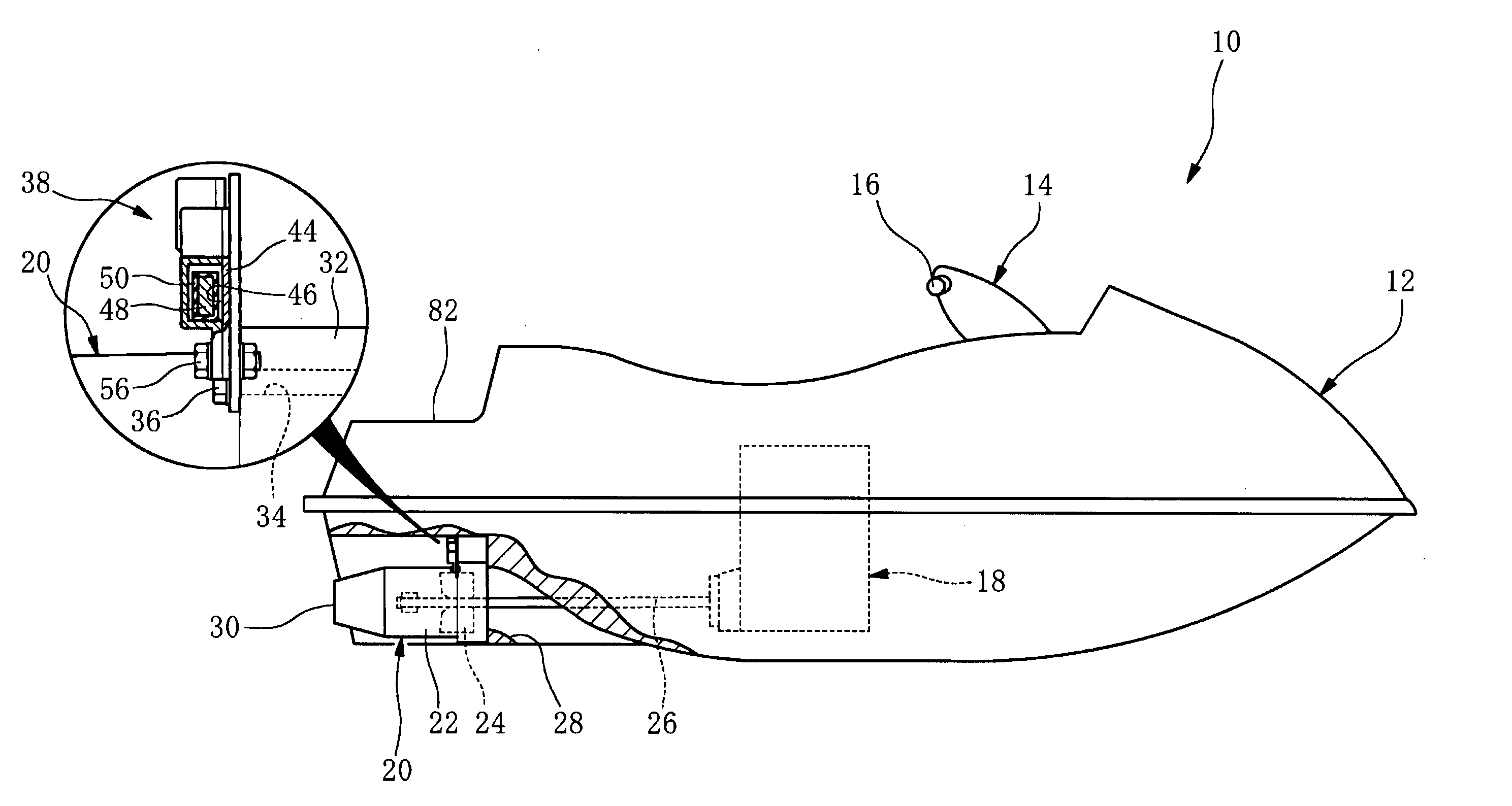
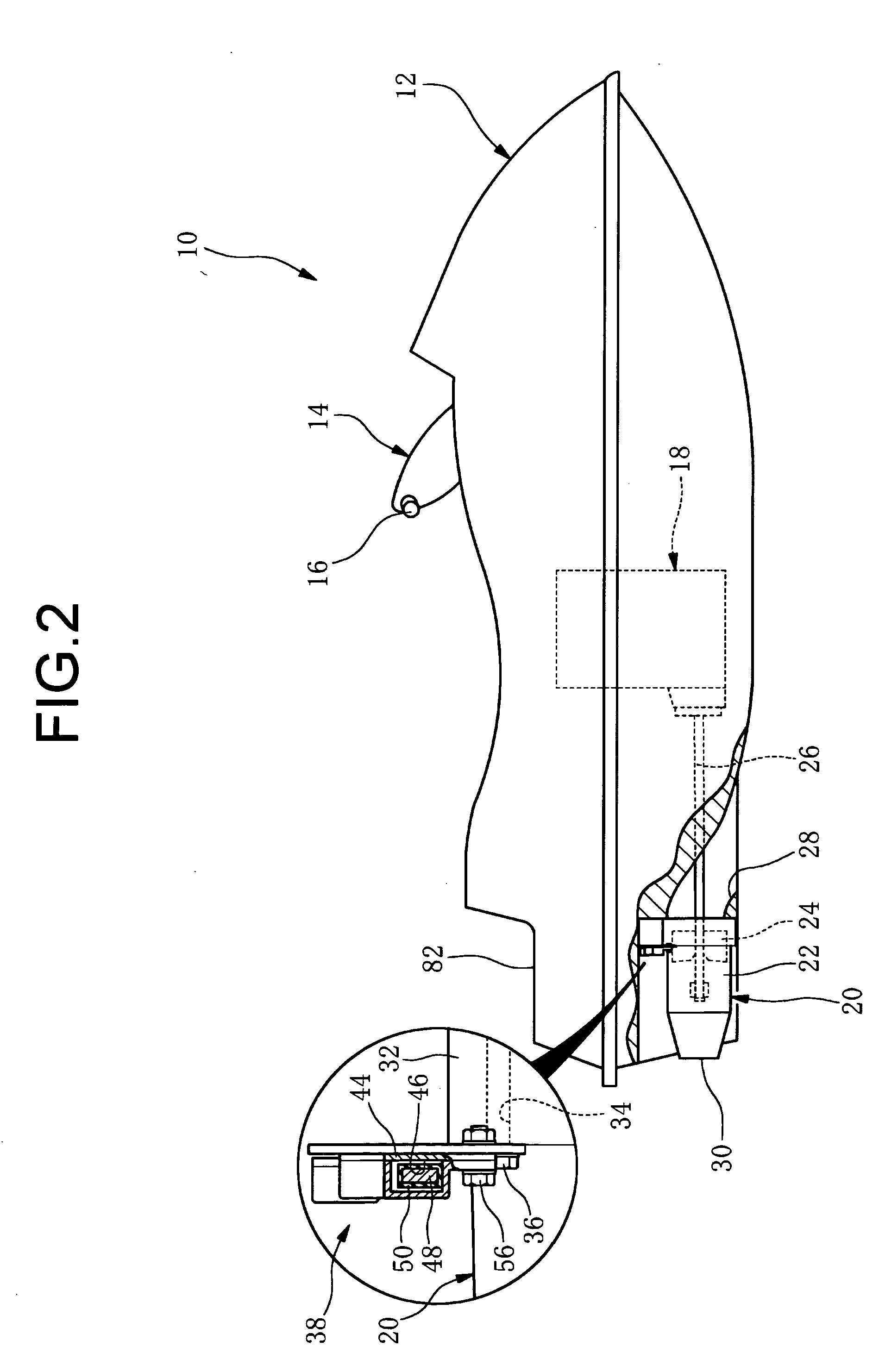
[0053] As illustrated in FIGS. 3 and 4, the jet pump 20 has a fixing flange 32 at the outer periphery of the pump housing 22, and is fixed to the hull 12 side by means of fixing bolts 36 threaded into fixing holes 34 (sea FIG. 3) in the fixing flange 32. A noise-reducing device assembly 38 of construction according to the invention is attached and fixed to the fixing flange 32 by which the jet pump 20 is fixed to the hull 12.

[0054] As illustrated in FIG. 4, the noise-reducing device assembly 38 in this embodiment has an attachment bracket 40, and a plurality (in this case, three) noise-reducing devices 42 fixed to a body portion 40a of the attachment bracket 40. The attachment bracket 40, which is rigid as a whole, is made of a member in the form of a plate, and is attached and fixed with its cantilever bars 40b, 40b to the fixing flange 32 by means of the fixing bolts 36 threaded into the fixing holes 34 in the fixing flange 32.

[0055] The plurality of noise-reducing devices 42 all...

second embodiment

[0062]FIGS. 6 and 7 illustrate the noise-reducing device assembly 38. As illustrated in FIG. 6, a plurality of (three in this case) noise-reducing devices 68 in this noise-reducing device assembly 38 as well are attached and fixed to the fixing flange 32 of the jet pump 20 by the attachment bracket 40 shared in common.

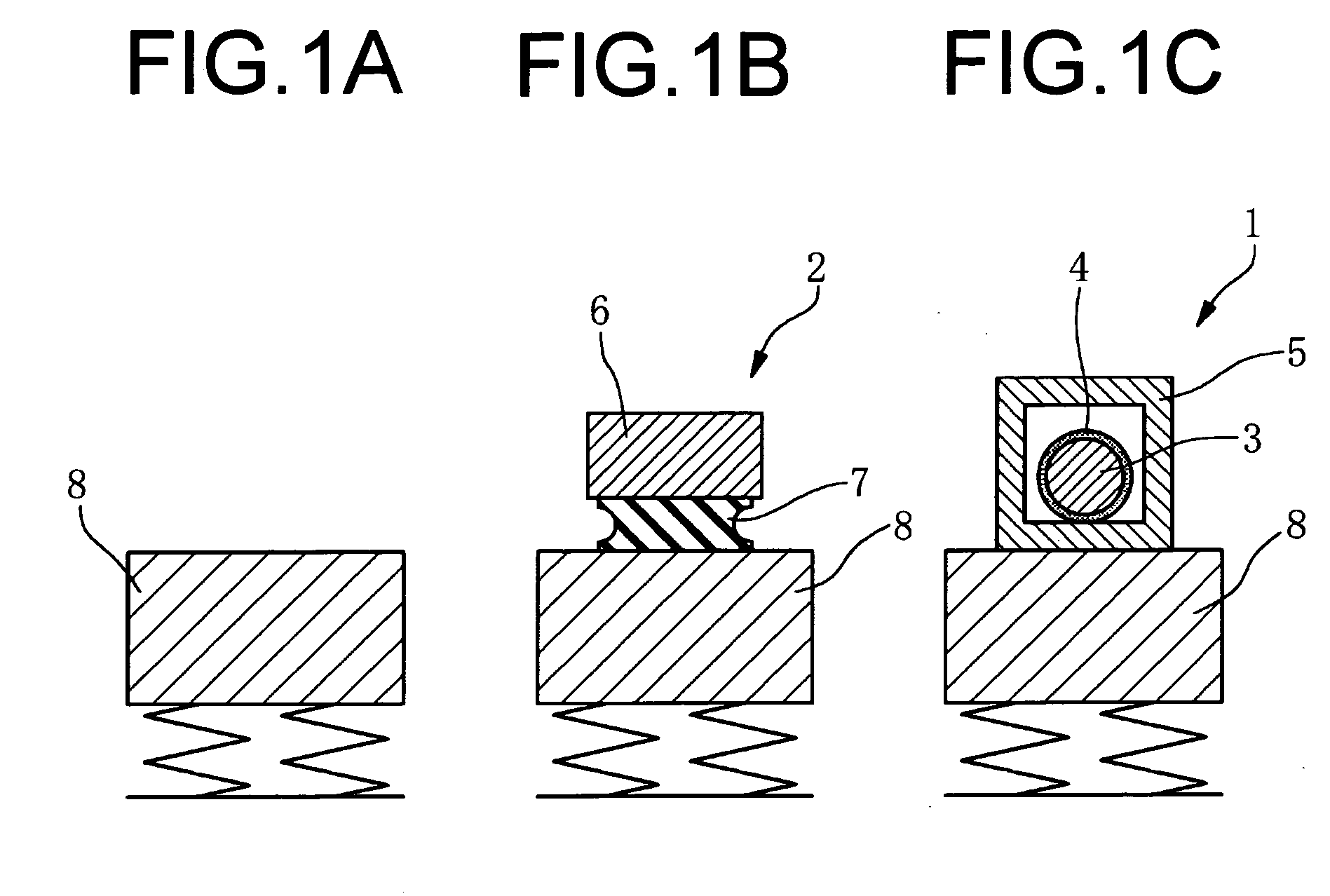
[0063]FIGS. 7A and 7B illustrate the specific structure of the noise-reducing device 68 in this noise-reducing device assembly 38. As illustrated, each noise-reducing device 68 in this embodiment has a dome-shaped rigid housing 70, inside of which a mass member 74 consisting of a ball coated on the surface with an elastic element 76 is housed freely moveable in three directions, by means of a certain gap therebetween.

[0064] As illustrated in FIGS. 6 and 7, each noise-reducing device 68 in this embodiment is equipped with a pair of arms 80 at the main body 78, and is fixed to the attachment bracket 40 shared in common by means of fixing bolts 56 at the arms 80. In the ...


PUM


Abstract

A noise-reducing device for water vehicles including: a rigid housing having a fluid-tightly sealed chamber formed therein, and fixable to a vibrating part of the water vehicle to be displaced with the vibrating part; a mass member housed in the rigid housing with a given gap therebetween so that the mass member is freely movable in the vibrating direction relative to the rigid housing, the mass member being adapted to come into collision with a contact part of the housing during input of vibration; and an elastic element formed on at least one surface of contact on the contact part or mass member.

Description

INCORPORATED BY REFERENCE [0001] The disclosure of Japanese Patent Application No. 2003-419127 filed on Dec. 17, 2003 including the specification, drawings and abstract is incorporated herein by reference in its entirety. BACKGROUND OF THE INVENTION [0002] 1. Field of the Invention [0003] The present invention relates to a noise-reducing device for water vehicles or other small vessels in which thrust is provided when water taken in by a jet pump is pressurized and accelerated, and is blasted to the rear by means of a jet nozzle. [0004] 2. Description of the Related Art [0005] Recently, there has been more widespread recreational use and the like of water vehicles in which thrust is provided when water taken in by a jet pump is pressurized and accelerated, and is blasted to the rear by means of a jet nozzle. The noise produced by such water vehicles when in use has been pointed out as a problem. [0006] To cope with this problem, several attempts have been made for reducing the noise...

Claims


Application Information

Patent Timeline
IPC IPC(8): B63B1/00B63B35/73B63H11/00B63H11/08B63H21/30F16F7/10F16F15/02G10K11/16
CPCB63B35/731B63H11/08F16F7/10B63H21/305B63H21/30B63B34/10G10K11/16
Inventor YAMADA, HIROSHIMARUYAMA, YUICHIROIWATA, HIDEAKISHIMIZU, DAISUKE
Owner SUMITOMO RIKO CO LTD
Why Eureka
Try Eureka