Tension controlled thread feeding system

a technology of tension control and thread feeding, which is applied in the direction of thin material processing, knitting, textiles and papermaking, etc., can solve the problems of unproductive downtime, high frictional force and tension level variations of threads or fibers, and high cohesive force of threads or fibers, and achieve fast and reliable methods.

Inactive Publication Date: 2005-06-23
INVISTA NORTH AMERICA R L
View PDF23 Cites 40 Cited by
  • Summary
  • Abstract
  • Description
  • Claims
  • Application Information

AI Technical Summary

Benefits of technology

[0034] The present invention is a system, apparatus and method for tension control in a thread feeding system that provides a fast and reliable method for feeding high tack elastomeric thread or fiber from a package to a thread processing system.

Problems solved by technology

This operation requires shutting down the manufacturing line causing unproductive downtime.
However, unacceptable variations in threadline tension are common with OETO.
However, threads or fibers that exhibit high cohesive forces (generally referred to as “tack”) display unusually high variations in frictional forces and tension levels as the package unwinds.
The slackness of the thread line in the relaxation region can vary and can result in temporarily excessive amounts of filament being unwound from the package.
This excess thread or fiber can be drawn into the nip rolls and wound up on itself leading to entanglement or breakage of the threadline requiring the manufacturing line to be stopped.
However, in this configuration, the thread or fiber in the region between the package and the nip rolls can sag.
This sagging allows the threadline position on the nip rolls to become unstable and can result in interference between adjacent threadlines.
However, Tiziano does not disclose the concept of utilizing a variable speed electrical motor for a driven roll, where the speed of the motor is determined based on a range of desired thread tensions, is not disclosed.
The aforementioned problems make the processing of high tack, elastomeric threads or fibers particularly problematic.
However, both approaches add additional expense.

Method used


Image

  • Tension controlled thread feeding system
  • Tension controlled thread feeding system
  • Tension controlled thread feeding system

Examples


example 1

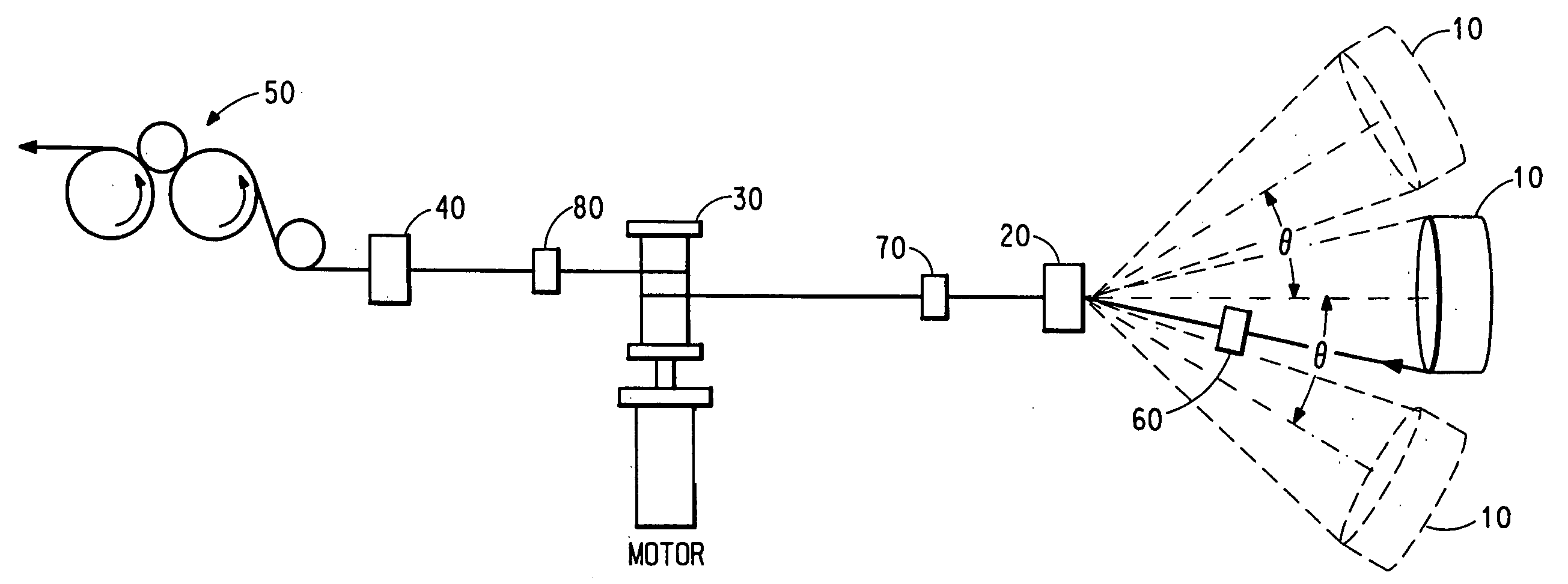
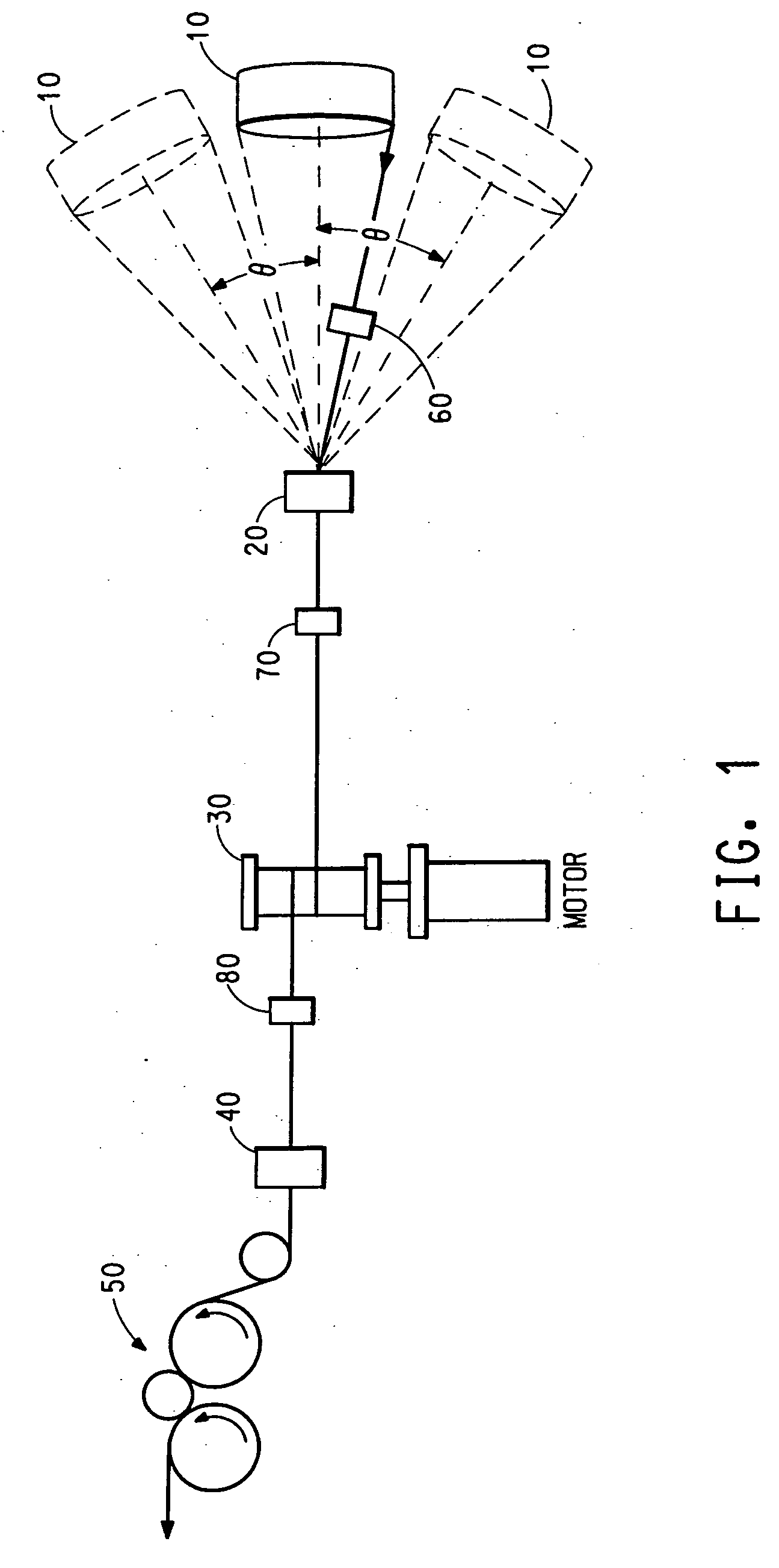
[0052] The test equipment used in obtaining the data for this and the following examples, could be configured in various ways, such as optionally including or excluding certain design elements and changing the sequence of certain elements. The equipment configuration employed for this example, with reference to FIG. 1, was comprised of the following elements, listed in the order in which they were encountered by the moving threadline: fiber package 10, static guide 20, first, driven roll 30, tension sensor 40, and driven take-up rolls 50.

[0053] The test equipment geometry and other experimental test conditions are summarized below:

[0054] The distances between the static guide 20 and the first driven roll 30, between the first driven roll 30 and the tension sensor 40 and between the first driven roll 30 and the take-up roll 50 were 0.22, 1.94 and 2.1-3.4 meters, respectively. In this example, the first driven roll 30, having a diameter of 8.89 cm. was not grooved. The threadline wa...

example 2

[0060] The same test equipment as described in Example 1, but configured to more closely correspond to the preferred embodiment of the OETO unwinder design was utilized. With reference to FIG. 1, the equipment had the following elements in the order in which they were encountered by the moving threadline: fiber package 10, captive rolling guide 60, static guide 20, captive rolling guide 70, first, driven roll 30, captive rolling guide 80, tension sensor 40, and driven take-up rolls 50.

[0061] The distances between the static guide 20 and the first driven roll 30, between the first driven roll 30 and the tension sensor 40, and between the first driven roll 30 and the take-up rolls 50 were 0.43, 0.51 and 2.43 meters, respectively. The first driven roll 30 was a single roll having a single groove with a depth of 0.38 mm. The threadline was again maintained in the horizontal plane. The distance between the package and the static guide 20 was held constant at 0.65 meter while the angle, ...

example 3

[0066] This series of runs, using the test equipment described previously and configured as in Example 2, evaluated the effect of angle on threadline tension for fibers of different tack levels. The distance, d, between the package and the static guide 20 was maintained constant at 0.65 meter. Threadline draft was maintained at 4× by controlling the first driven roll 30 and the take-up rolls 50, respectively, at surface speeds of 68.6 and 274.3 meters / min. All other experimental conditions were as described for Example 2. The data are summarized in Table 3.

TABLE 3MeanMax.AngleRangeTensionTensionFiber(decree)Tension (g)(grams)SpikesTackT-162C025.1164.727.02 800 dtex525.1157.70″Merge 166001127.5156.90″Lot 00202228.2160.00″4536.9182.816″5742.4196.159″6747.8>200.0127″77BROKET-162C018.8150.601.408As-spun515.7142.80″840 den1117.3143.50″Merge 167952214.9140.40″Lot 10194514.9138.80″57″6715.7140.40″9017.3145.10″T-162 B029.0171.81311.368 800 dtex532.2172.610″Merge 165251136.1184.342″Lot 020...


PUM

PropertyMeasurementUnit
wrap angleaaaaaaaaaa

Abstract

A system, apparatus and method for tension control in a thread feeding system that provides a fast and reliable method for feeding high tack elastomeric thread or fiber from a package to a thread processing system. A drive and tension control apparatus at least one of increments, maintains or decrements the speed of a driven take-off roll when the tension is out of a predetermined range of operation. A tension controller devices measures tension and determines whether the average tension for the moving threads is out-of-range relative to the predetermined tension values for the threads. Alarms and other indicators may also be used to determine the threads are at least one of broken, not moving and out-of-range for tension control.

Description

CROSS-REFERENCE TO RELATED APPLICATION [0001] This application is a continuation-in-part of U.S. patent application Ser. No. 10 / 722,261, filed Nov. 25, 2003.BACKGROUND OF THE INVENTION [0002] 1. Field of the Invention [0003] The present invention relates to a thread feeding system or fiber unwinding device, and more specifically to a system or device that minimizes average tension levels and tension variations of a plurality of elastomeric threads or fibers being transported to a downstream thread or fiber processing operation. [0004] 2. Description of Background Art [0005] The most common method of unwinding thread or fiber from a cylindrical mandrel (or “package”) in manufacturing processes is referred to as “rolling takeoff”. It should be noted that the terms “thread” or “fiber” are used interchangeably throughout this document. When the package is exhausted the empty mandrel must be removed and a new package installed. This operation requires shutting down the manufacturing line...

Claims


Application Information

Patent Timeline
Patent Type & Authority Applications(United States)
IPC IPC(8): B65H49/02B65H49/16B65H51/32B65H57/16D04B15/50
CPCB65H49/02B65H49/16B65H2701/319B65H57/16B65H59/388B65H51/32
Inventor HEANEY, DANIEL J.GRAVERSON, JON P.HICKS, DENNIS G.MARTIN, KENNETH E.HARTZHEIM, RICHARD J.
Owner INVISTA NORTH AMERICA R L
Why Eureka
Try Eureka