
Pulse width modulation controller with double pulse immunity

Active Publication Date: 2005-06-23
TEXAS INSTR INC
View PDF1 Cites 17 Cited by
  • Summary
  • Abstract
  • Description
  • Claims
  • Application Information

AI Technical Summary

Benefits of technology

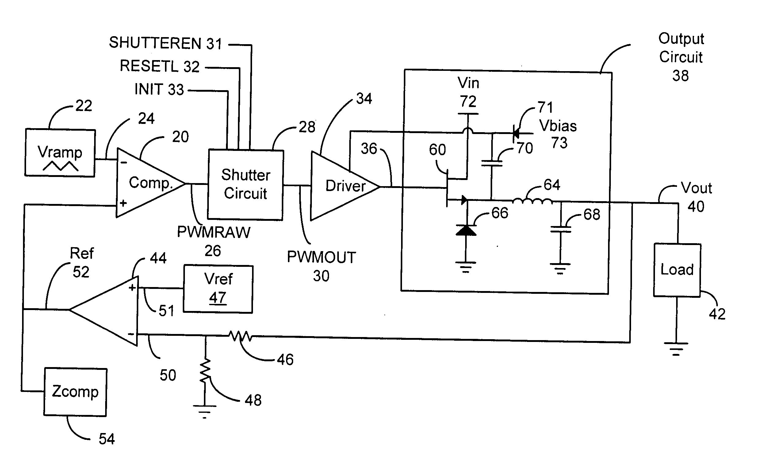
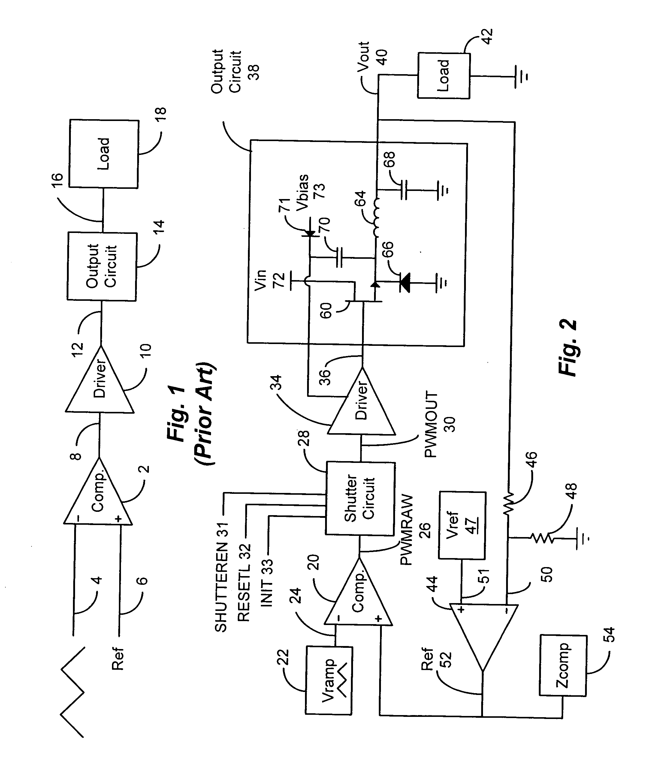
[0009] In accordance with the present invention, a pulse width modulation controller having a shutter circuit is disclosed. The disclosed PWM controller includes a comparator that generates a raw PWM signal from either an analog input waveform having periodic and generally symmetric positively and negatively sloped ramp portions or alternatively a periodic sawtooth waveform having a ramped edge and a rapidly transitioning edge. The raw PWM signal is coupled to the input of the shutter circuit and the shutter circuit produces a PWM output signal. The shutter circuit eliminates double pulsing that may be present on the raw PWM signal.
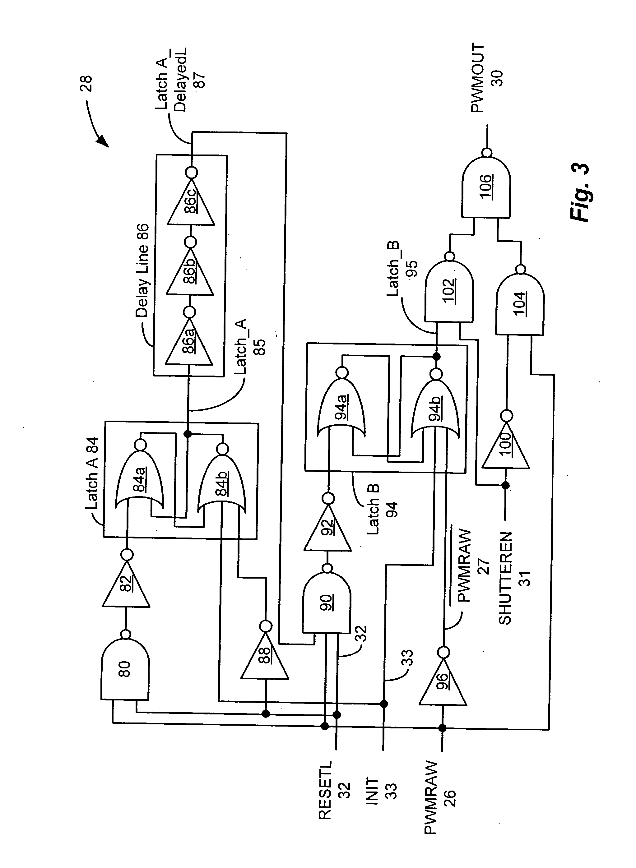
[0010] The shutter circuit employs a first latch that is used to arm the second latch. More specifically, in response to the detection of a threshold crossing in a first direction by the comparator, the first latch is set. The second latch is set concurrently with the first latch and once the first latch is set, the second latch is armed to reset upon the detection of a threshold crossing in a second direction by the comparator, wherein the second direction is opposite to the first direction. The first latch is reset periodically by a high speed one-shot at a point in time when the voltage of the periodic analog input signal to the comparator is not near the reference voltage. The output of the second latch corresponds to the output of the shutter circuit. In the foregoing manner the shutter circuit prevents double pulsing at the shutter circuit output.

Problems solved by technology

Such undesirable pulsing can introduce an undesirable error component into the PWM output signal in the form of repeated pulses.
In the case in which a generally symmetric triangular waveform is used as the analog input signal, noise could potentially produces double pulsing of the PWM signal at locations corresponding to reference voltage crossings by either the positive or negative going ramps of the analog input waveform.

Method used


Image

  • Pulse width modulation controller with double pulse immunity
  • Pulse width modulation controller with double pulse immunity
  • Pulse width modulation controller with double pulse immunity

Examples


Embodiment Construction

[0019] In accordance with the present invention, a pulse width modulation controller having a shutter circuit is disclosed. Referring to FIGS. 2-4 the disclosed PWM controller includes a comparator 20 that generates a raw PWM signal PWMRAW 26 from a waveform generator 22 that generates either an analog input waveform having periodic positively and negatively sloped ramped portions or alternatively, a periodic sawtooth waveform having a ramped edge and a rapidly transitioning edge. The raw PWM signal PWMRAW 26 is coupled to the input of a shutter circuit 28 and the shutter circuit 28 produces a PWM output signal PWMOUT 30 that eliminates instances of double pulsing that are present on the PWMRAW signal 26. As used herein, the term double pulsing is used generally to describe undesired repeating pulsing of the shutter circuit output whether such pulsing involves two or more pulses within a specified periodic interval.

[0020] The comparator 20 receives as inputs a periodic waveform 24 ...


PUM


Abstract

A pulse width modulation (PWM) controller includes a shutter circuit interposed between a PWM modulator and a driver circuit. The shutter circuit receives a raw PWM output signal from the PWM modulator and processes the raw PWM signal to eliminate double pulsing that may be present on the raw PWM signal. Bypass logic responsive to a switch or software controlled enable input is provided to permit the shutter circuit to be included in the PWM controller or alternatively, to be bypassed.

Description

CROSS REFERENCE TO RELATED APPLICATIONS [0001] Not Applicable STATEMENT REGARDING FEDERALLY SPONSORED RESEARCH OR DEVELOPMENT [0002] Not Applicable BACKGROUND OF THE INVENTION [0003] The present invention relates to a pulse width modulator that provides double pulse immunity in a high speed pulse width modulation (PWM) controller. [0004] Pulse width modulators are often employed in motor and power controllers. Techniques for the generation of a pulse with modulated signal are well known in which a digital signal is employed to power a device or drive a motor and the duty cycle of the digital signal is varied to determine the power delivered to the load. In such a system an analog waveform is converted into a pulse width modulated signal. If the analog waveform is a generally symmetric triangular waveform, a comparator is typically used to produce both transitions of the pulse width modulated digital signal, i.e. when the portion of the analog waveform having a positive slope crosses...

Claims


Application Information

Patent Timeline
IPC IPC(8): H02M3/156H03K5/1252
CPCH02M3/156H03K5/1252H02M2001/0041H02M1/0041
Inventor SANZO, CHRISTOPHER J.TATEISHI, TETSUO
Owner TEXAS INSTR INC
Learn More