Color image sensor with imaging elements imaging on respective regions of sensor elements

a color image sensor and imaging element technology, applied in the field of color image sensors with imaging elements, can solve the problems of many problems with certain types of subjects, false colors, and market pressure to reduce the size of the sensor, and achieve the effect of reducing the area of each region of the light sensor, reducing the size of the sensor, and speeding up the read-out tim

Active Publication Date: 2005-06-23
MICRON TECH INC
View PDF13 Cites 153 Cited by
  • Summary
  • Abstract
  • Description
  • Claims
  • Application Information

AI Technical Summary

Benefits of technology

[0016] Embodiments of the invention generate a color image signal without using a color mosaic filter. Dispensing with the color mosaic filter allows the area of each region of the light sensor to be reduced compared with the area of the conventional light sensor. This allows the imaging elements to be made smaller and be located to the light sensor. Moreover, in embodiments in which the images are formed in narrow-band light, the imaging elements can be simpler and therefore smaller than conventional imaging elements. In some embodiments, the imaging elements incorporate diffractive elements that ar

Problems solved by technology

Such products are subject to market pressure to reduce them in size, or to pack more features into a product of a given size.
The need to synthesize the missing electrical values in conventional light sensor 12 causes many problems with certain types of subject when a picture is displayed in response to the color image signal.
Adjacent areas of the picture with sharp color differences can produce false colors.
Almost horizontal or vertical lines are displayed with jagged edges and can exhibit color problems.
Another problem of conventional light sensor 12 is that light leakage from one sensor element to a neighboring sensor element not only causes blurring in the displayed pictu

Method used


Image

  • Color image sensor with imaging elements imaging on respective regions of sensor elements
  • Color image sensor with imaging elements imaging on respective regions of sensor elements
  • Color image sensor with imaging elements imaging on respective regions of sensor elements

Examples


Embodiment Construction

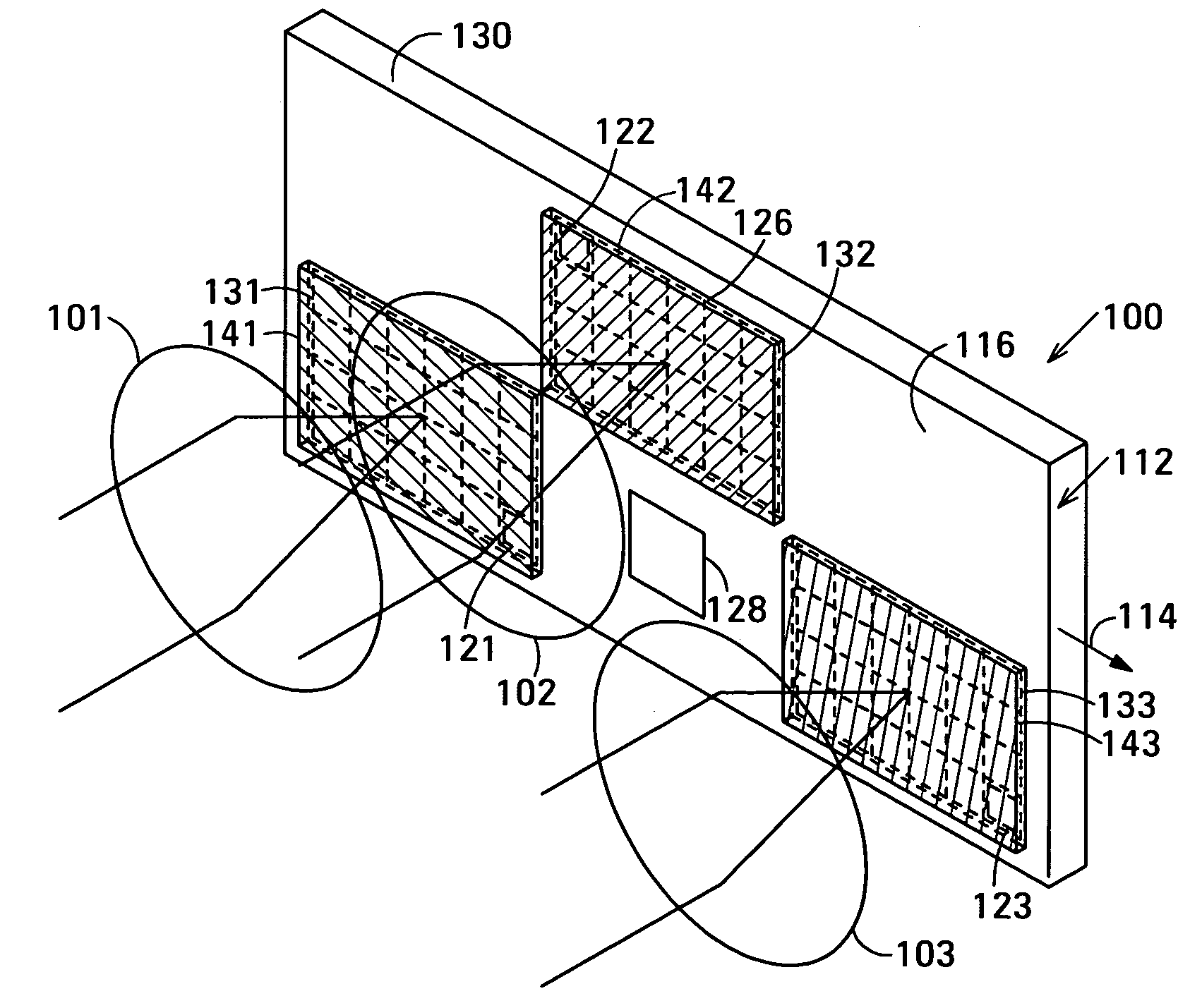
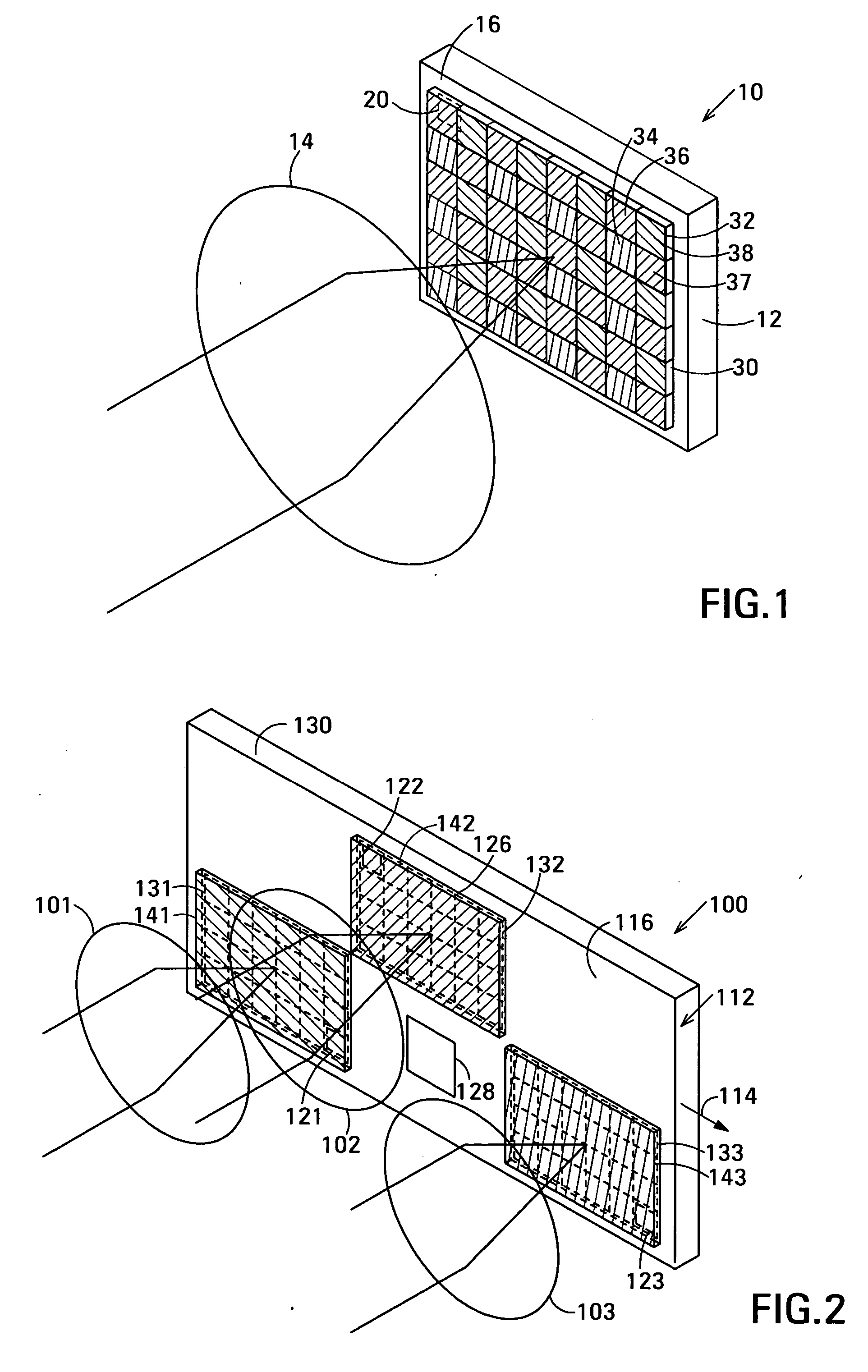
[0035]FIG. 2 is an isometric view of a highly simplified first embodiment 100 of a color image sensor in accordance with the invention. Color image sensor 100 generates a color image signal representing a subject and is composed of a light sensor 112 and imaging elements shown schematically at 101, 102 and 103. Light sensor 112 has sensor elements arranged on its major surface 116. In operation, the light sensor generates a color image signal 114 in response to light incident on major surface 116. Imaging elements 101, 102 and 103 are arranged to form images of the subject in light of different colors on respective regions 131, 132 and 133 of light sensor 112. The regions of the light sensor on which the images are formed are substantially spatially separated to prevent light leakage among the images.

[0036] In color image sensor 100, the sensor elements are arranged in an irregular array in which each of regions 131, 132 and 133 is composed of a rectangular array of sensor elements...


PUM


Abstract

The color image sensor generates an image signal representing a subject. The color image sensor has a light sensor and imaging elements arranged to form images of the subject in light of different colors on respective regions of the light sensor. The light sensor includes sensor elements and is operable to generate the image signal in response to light incident on it.

Description

RELATED APPLICATION [0001] This application is related to U.S. patent application Ser. No. ______ of Russell W. Gruhlke and Dale W. Schroeder entitled Color Image Sensor having Imaging Element Array Forming Images on Respective Regions of Sensor Elements (Agilent Docket No. 10031572) filed on the filing date of this application and incorporated into this application by reference.BACKGROUND [0002] Electronic image sensors are incorporated not only in digital cameras but, more recently, also into such consumer electronic products as mobile telephones and personal digital assistants (PDAs). Such products are subject to market pressure to reduce them in size, or to pack more features into a product of a given size. [0003]FIG. 1 is a schematic isometric view of a highly simplified example of a typical conventional color image sensor 10 found in present day products such as digital cameras, mobile telephones and PDAs. Image sensor 10 is composed of a single light sensor 12 and a single im...

Claims


Application Information

Patent Timeline
IPC IPC(8): H04N5/225H04N5/353H04N5/359H04N5/369H04N9/04H04N9/09H04N9/097
CPCH04N5/2253H04N9/097H04N9/093H04N9/045H04N23/54H04N25/41H04N23/843H04N25/11H04N23/15H04N23/16
Inventor SCHROEDER, DALE W.GRUHLKE, RUSSELL W.
Owner MICRON TECH INC
Why Eureka
Try Eureka