Optoelectronic arrangement having at least one laser component, and a method for operating a laser component

a technology of laser components and optical arrangement, which is applied in the direction of lasers, semiconductor laser structural details, semiconductor lasers, etc., can solve the problems of laser aging and addition of load, and achieve the effect of allowing wavelength stabilization of laser diodes, simple and cost-effectiv

Inactive Publication Date: 2005-06-23
INFINEON TECH AG
View PDF4 Cites 8 Cited by
  • Summary
  • Abstract
  • Description
  • Claims
  • Application Information

AI Technical Summary

Benefits of technology

[0006] The object of the present invention is to make available an optoelectronic arrangement having at least one laser component, and a method for operating a laser component that permits wavelength stabilization of a laser diode in a simple and cost effective way. SUMMARY OF THE INVENTION
[0008] The solution according to the invention manages without use of a Peltier cooler and without a cooling of the laser component previously employed for the purpose of wavelength stabilization. It is consequently simple and cost-effective to implement. The solution according to the invention departs from the principle previously used in the prior art of cooling the laser component in order to stabilize the wavelength it emits. Instead of this, the laser component is additionally heated during operation. The laser component is then operated at a temperature that is equal to or somewhat above the highest operating temperature of the laser to be expected that would arise without heating. Such a highest operating temperature to be expected can be determined in a simple way experimentally and constitutes a known parameter of a laser component.
[0011] Overall, the present invention provides a cost effective configuration of an optoelectronic transmission arrangement that permits the output wavelength of a laser component to be stabilized in a simple way.
[0012] A heating device for heating the laser component can fundamentally be designed in any desired way. It is preferably formed in a simple way by electrical connections with an increased ohmic electrical resistance that are provided locally at specific locations of the optoelectronic arrangement. In a preferred refinement, the heating device is integrated in the laser component itself. This has the advantage that only the laser component itself is to be heated, and thus the required heating power is minimized.
[0016] In a preferred refinement of the invention, a temperature sensor is dispensed with and, instead of this, a device is provided for the direct optical detection of the emitted wavelength of the laser component, the output signal of this device being fed, in turn, to a controlling device for controlling the temperature of the laser component. In the case of this configuration, the operating point of the laser component is therefore monitored by means of a direct optical detection of the wavelength. This permits a finer stabilization of the wavelength than by means of a temperature sensor.

Problems solved by technology

The inventive operation of the laser component at an increased temperature certainly has a disadvantage that the laser is additionally loaded, and aging of the laser occurs more quickly.

Method used


Image

  • Optoelectronic arrangement having at least one laser component, and a method for operating a laser component
  • Optoelectronic arrangement having at least one laser component, and a method for operating a laser component
  • Optoelectronic arrangement having at least one laser component, and a method for operating a laser component

Examples


Embodiment Construction

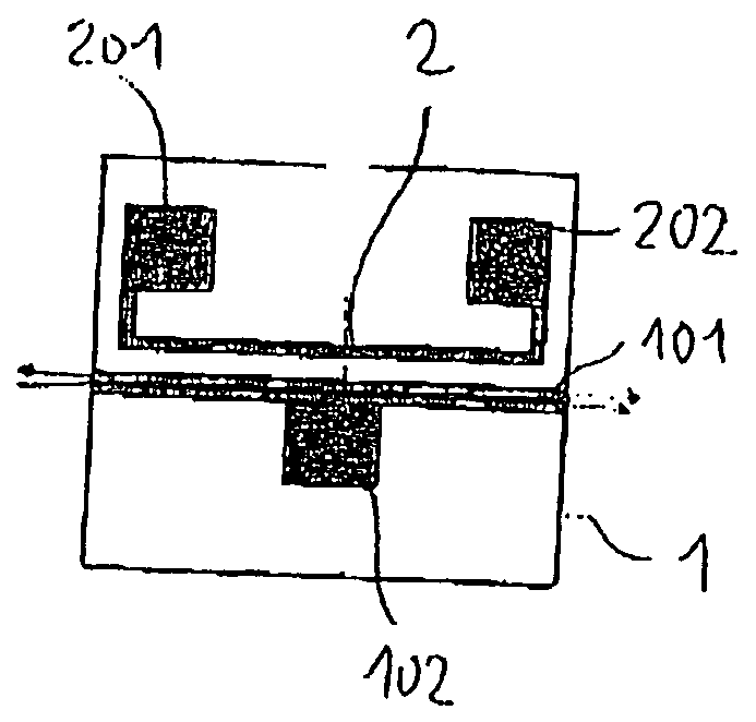
[0032]FIG. 1 shows a plan view of a laser diode chip 1 with a laser channel 101 in which a stimulated emission of photons takes place. The laser diode is designed as an edge emitter in the exemplary embodiment illustrated, and so the laser light emerges from the laser channel 101 at the end face, as indicated by arrows. A first metallization or a first bonding pad 102 serves as an electrical connector contact. A second metallization is arranged in a corresponding way on the underside of the chip 1.

[0033] Running parallel to the laser channel 101 is a resistance heater that is formed by a resistance conductor track 2 with an ohmic resistance. Electrical contact is made with the resistance conductor track 2 via two contacts or bonding pads 201, 202, and it is heated by the flow of current. The heating power of the resistance heater can be set in this case via the applied voltage.

[0034] The resistance heater 2 is located relatively near the laser channel 101 such that a relatively lo...


PUM

PropertyMeasurementUnit
wavelengthaaaaaaaaaa
angleaaaaaaaaaa
constant temperatureaaaaaaaaaa

Abstract

The invention relates to an optoelectronic arrangement having at least one laser component. A heating device for heating the laser component up to a constant temperature is provided in such a way that the laser component is operated at a temperature that is at least equal to the highest temperature to be expected that would be present during operation of the laser component without the heating device. The invention also relates to a method for operating a laser component in which the laser component is heated up to a constant temperature that is at least equal to the highest temperature to be expected that would be present during operation of the laser component without heating. The laser component is then operated at this temperature. The exact monitoring of the emitted wavelength of a laser component is rendered possible in a simple way by the invention.

Description

[0001] The invention relates to an optoelectronic arrangement having at least one laser component, and to a method for operating a laser component. It permits the exact setting and monitoring of the emitted wavelength of a laser component. BACKGROUND OF THE INVENTION [0002] For the purpose of transmitting as large a quantity of data as possible via an optical waveguide, it is known in optical telecommunications to multiplex the data to be transmitted. One possibility for this purpose is to transmit information independently and simultaneously over one waveguide with the aid of several wavelengths (wavelength division multiplexing—WDM). It is necessary in this case to keep reliably on the transmission side to the various prescribed optical wavelength channels. Thus, there is a need in the transmission modules for an optical arrangement with the aid of which the wavelength of the individual transmission devices can be monitored and, if required, corrected. The aim in this case is for ...

Claims


Application Information

Patent Timeline
Patent Type & Authority Applications(United States)
IPC IPC(8): H01S3/04H01S5/00H01S5/02H01S5/022H01S5/024H01S5/0683
CPCH01S5/005H01S5/0071H01S5/02212H01S5/0683H01S5/02292H01S5/02453H01S5/02276H01L2224/49171H01S5/0261H01S5/02255H01S5/02345
Inventor KROPP, JORG-REINHARDT
Owner INFINEON TECH AG
Why Eureka
Try Eureka