Method and system for simultaneously viewing rendered volumes

a technology of rendering volume and volume, applied in the field of medical imaging, can solve the problems of easy missed small structures present in a single slice, difficult to evaluate the three-dimensional volumetric image in clinical practice, and associated loss of contrast, and achieve the effect of reducing artifacts

Inactive Publication Date: 2005-06-23
GENERAL ELECTRIC CO
View PDF3 Cites 146 Cited by
  • Summary
  • Abstract
  • Description
  • Claims
  • Application Information

AI Technical Summary

Benefits of technology

[0007] The present technique provides a novel approach to visualizing three-dimensional data, referred to as volumetric images, such as data provided by tomosynthesis imaging systems. In particular, the present technique provides for the use of weighting functions, such as depth-dependent weighting functions, in the determination of pixel values in the volume rendered image from voxel values in the volumetric image. Weighting functions may modify the voxel value itself and / or other modifiers of the voxel value, such as opacity functions. Furthermore, the technique provides for novel viewing modes, such as varying the volume of interest via the weighting function or functions. Other novel viewing modes may include varying the view angle to reduce artifacts attributable to the scan trajectory and simultaneously displaying different volume renderings with common reference image data but different perspectives.

Problems solved by technology

However, evaluating the three-dimensional volumetric image may pose challenges in clinical practice.
Therefore, small structures present in a single slice may be easily missed.
However, one drawback of many volume rendering methods is an associated loss of contrast, which may more than offset gains in contrast achieved by the three-dimensional reconstruction process.
This problem typically occurs when showing the full volume from a view angle requires some type of averaging of values of the volumetric image for a range of depths.
In addition, if a structure of interest is not located “close to the viewpoint,” i.e., in front of most other structures, as seen from the viewpoint, occlusion effects may further diminish the contrast of the structure, or even hide it completely.

Method used


Image

  • Method and system for simultaneously viewing rendered volumes
  • Method and system for simultaneously viewing rendered volumes
  • Method and system for simultaneously viewing rendered volumes

Examples


Embodiment Construction

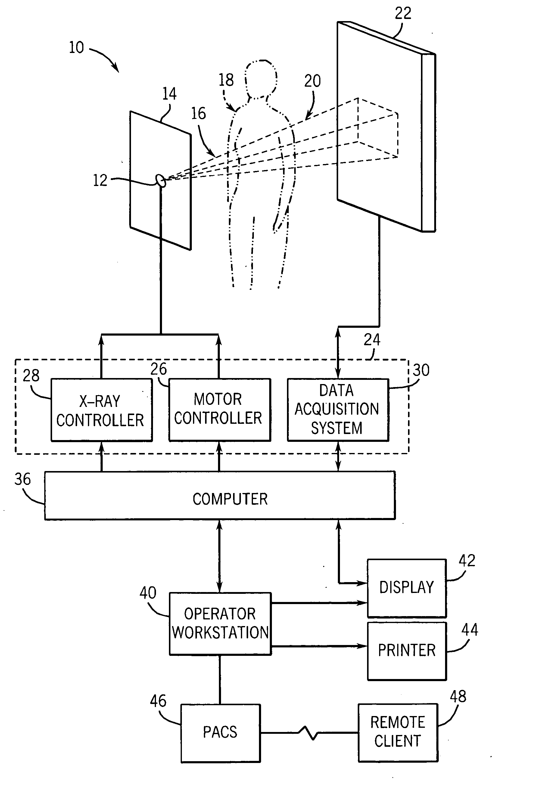
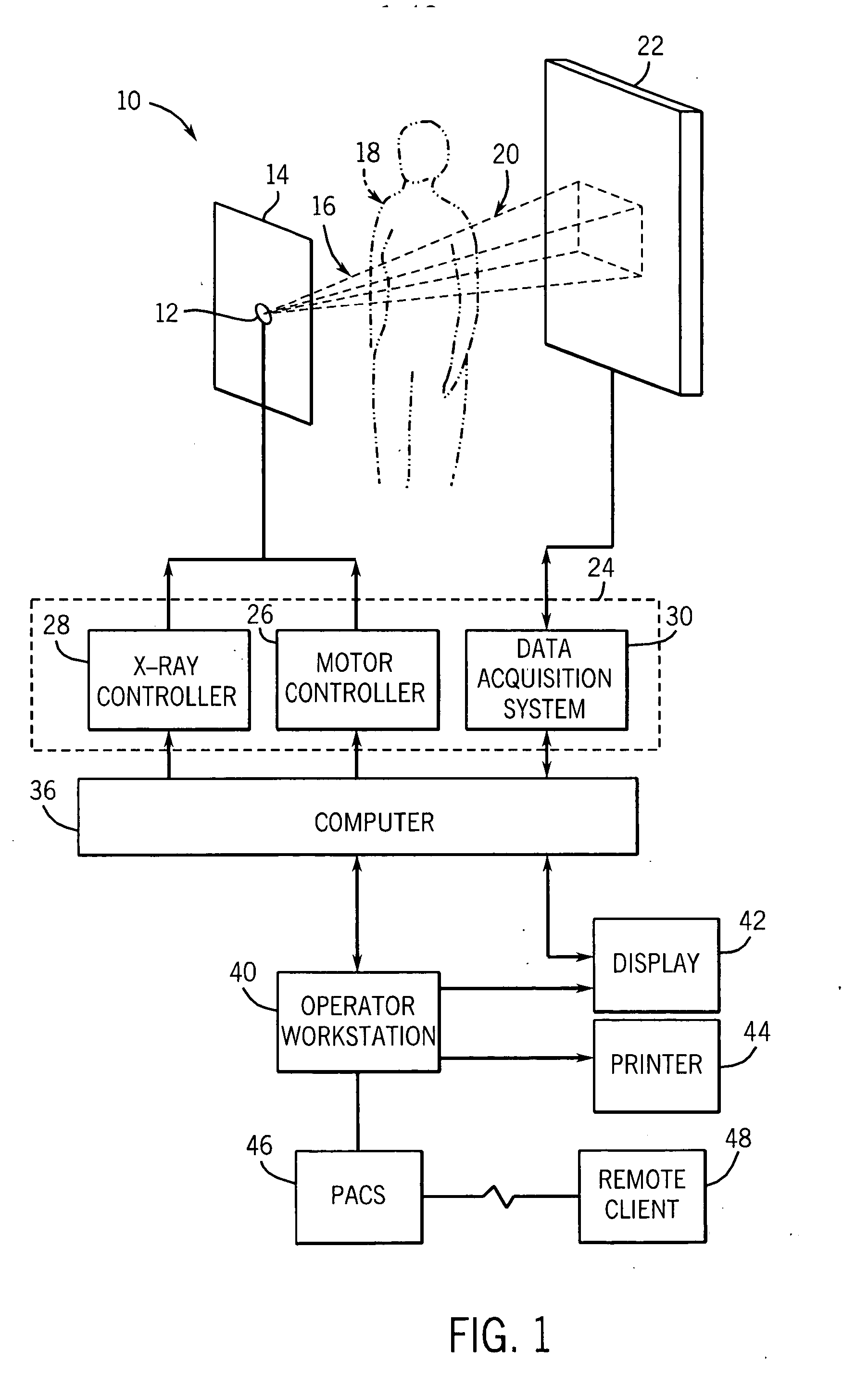
[0013] In the field of medical imaging, various imaging modalities may be employed to non-invasively examine and / or diagnose internal structures of a patient using various physical properties. One such modality is tomosynthesis imaging which utilizes a limited number of projection radiographs, typically twenty or less, each acquired at a different angle relative to a patient. The projection radiographs may then be combined to generate a volumetric image representative of the imaged object, i.e., a three-dimensional set of data that provides three-dimensional context and structure for the volume of interest. The present technique addresses visualization issues that may arise in the display of volumetric images provided by tomosynthesis imaging. In particular, the present technique allows for the incorporation of weighting into the visualization process and for various viewing modes that may benefit from such weighting.

[0014] An example of a tomosynthesis imaging system 10 capable of...


PUM

PropertyMeasurementUnit
view angleaaaaaaaaaa
volumesaaaaaaaaaa
volume renderingaaaaaaaaaa

Abstract

A technique is provided for concurrently viewing volumes that may be rendered using visualization techniques incorporating one or more functions, such as depth-dependent weighting functions. In one aspect, the viewing technique may provide for the concurrent viewing of volumes, such as overlapping volumes, from different viewpoints. In accordance with this aspect, the relative position of display may convey the relative viewpoints. In addition, the viewing technique may provide for concurrently displaying volume renderings of a volume in which the volume renderings are generated using different functions, such as weighting and / or transfer functions. In this manner, the effect of the functions on visual properties of structures within the volume may be observed.

Description

BACKGROUND OF THE INVENTION [0001] The present invention relates generally to the field of medical imaging, and more specifically to the field of tomosynthesis. In particular, the present invention relates to the visualization of reconstructed volumes from data acquired during tomosynthesis. [0002] Tomosynthesis is an imaging modality that may be used in a medical context to allow physicians and radiologists to non-invasively obtain three-dimensional representations of selected organs or tissues of a patient. In tomosynthesis, projection radiographs, conventionally known as X-ray images, are acquired at different angles relative to the patient. Typically, a limited number of projection radiographs are acquired over a relatively small angular range. The projections comprising the radiographs generally reflect interactions between x-rays and the imaged object along the respective X-ray paths through the patient and, therefore, convey useful data regarding internal structures. From the...

Claims


Application Information

Patent Timeline
Patent Type & Authority Applications(United States)
IPC IPC(8): A61B6/03G06T11/00
CPCA61B6/025A61B6/4021G06T2211/436G06T11/008A61B6/463
Inventor CLAUS, BERNHARD ERICH HERMANNEBERHARD, JEFFREY WAYNE
Owner GENERAL ELECTRIC CO
Why Eureka
Try Eureka