Developing roller, developing apparatus, process cartridge, and image formation apparatus

a development roller and development apparatus technology, applied in the direction of shafts and bearings, permanent magnets, instruments, etc., can solve the problems of difficult to obtain good-quality images, difficult to improve both high density and low density portions at the same time, and the trailing edge of a black solid image or a halftone solid image tends to be lost, so as to achieve the effect of reducing the deposition of carriers

Active Publication Date: 2005-06-23
RICOH KK
View PDF22 Cites 26 Cited by
  • Summary
  • Abstract
  • Description
  • Claims
  • Application Information

AI Technical Summary

Benefits of technology

[0011] It is an object of the present invention to provide a developing roller, developing apparatus, process cartridge, and image formation apparatus with which the above problems encountered in the past can be solved, greasing and so forth can be prevented, and carrier deposition can be reduced.

Problems solved by technology

With a conventional two-component developing type of developing apparatus, the developing conditions for raising image density are incompatible with the developing conditions for obtaining an image with good contrast, making it difficult to improve both a high density portion and a low density portion at the same time.
In other words, these two developing conditions are contradictory, and it is generally difficult to obtain a good-quality image by satisfying both conditions over the entire image density range.
For instance, when the emphasis is on obtaining a low-contrast image, the trailing edge of a black solid image or a halftone solid image tends to be lost, which also occurs with the crossing portions of solid lines.
The deposited carrier is transferred and fixed along with the toner on the paper, which has an adverse effect on the transfer apparatus and fixing apparatus, and is a cause of lower reliability of an image formation apparatus.
In order to prevent carrier deposition, the charge potential of the latent image support or the potential of the developing roller is sometimes adjusted so as to reduce the electrical force to which the carrier is subjected, but this tends to result in image problems such as greasing.

Method used


Image

  • Developing roller, developing apparatus, process cartridge, and image formation apparatus
  • Developing roller, developing apparatus, process cartridge, and image formation apparatus
  • Developing roller, developing apparatus, process cartridge, and image formation apparatus

Examples


Embodiment Construction

[0032] Embodiments of the present invention will now be described through reference to the appended drawings.

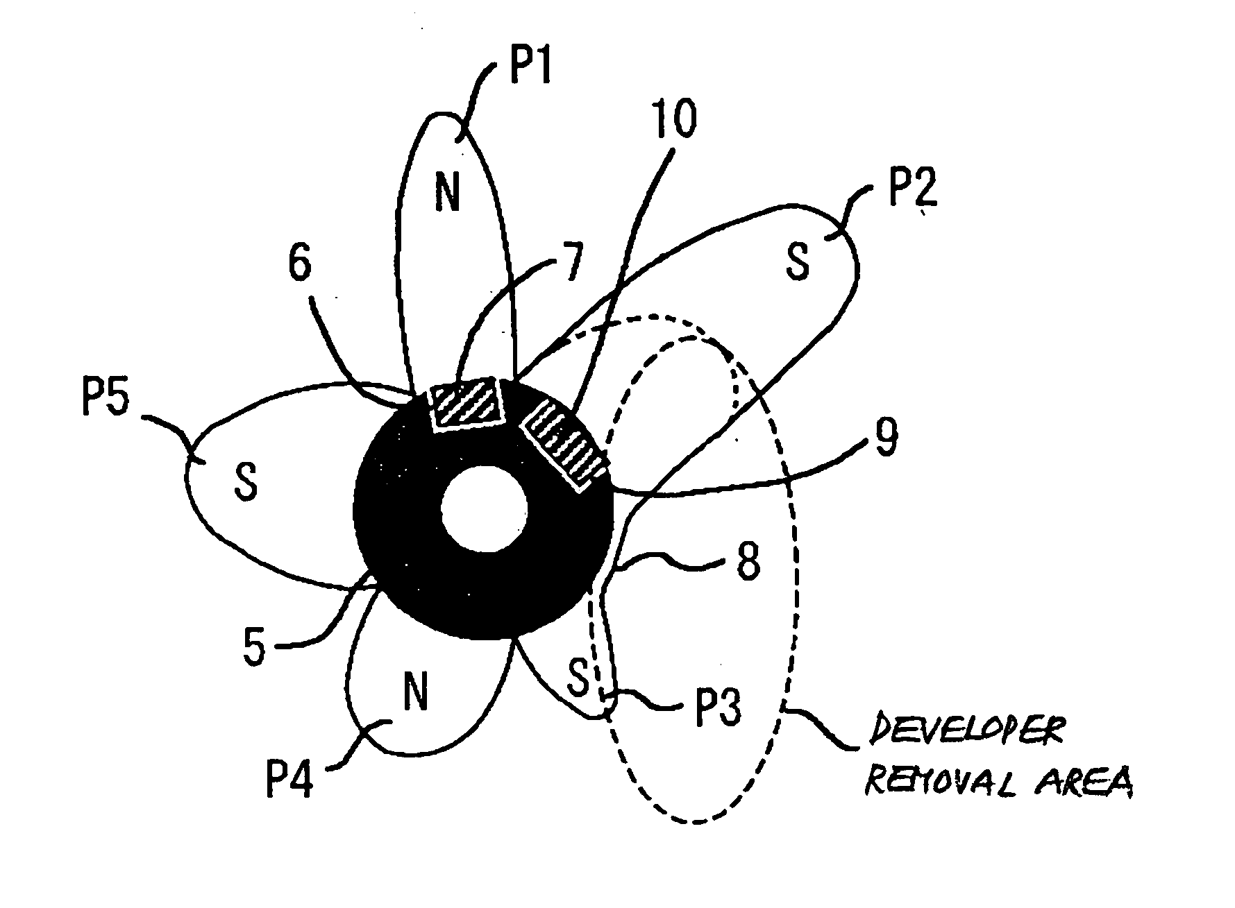
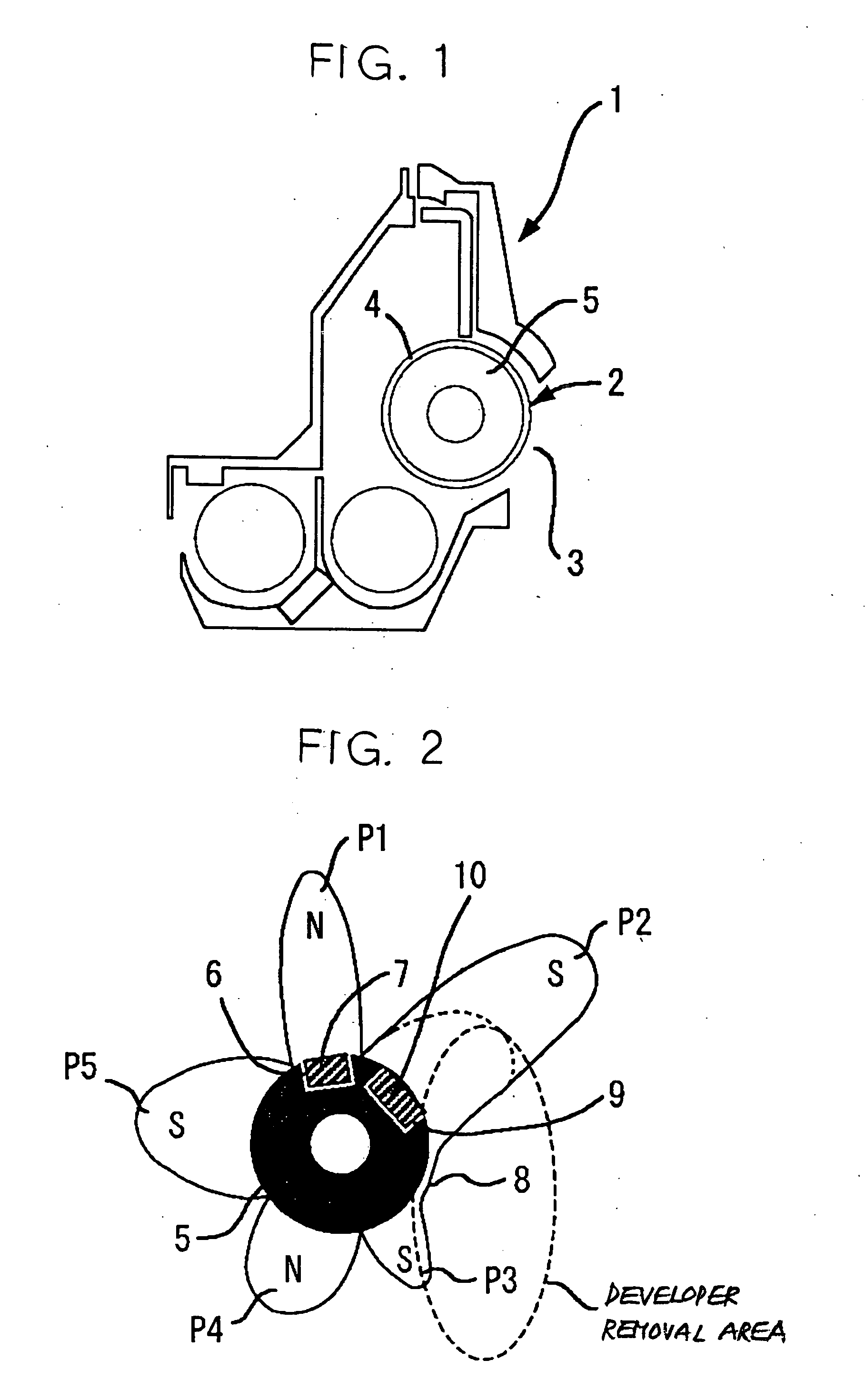
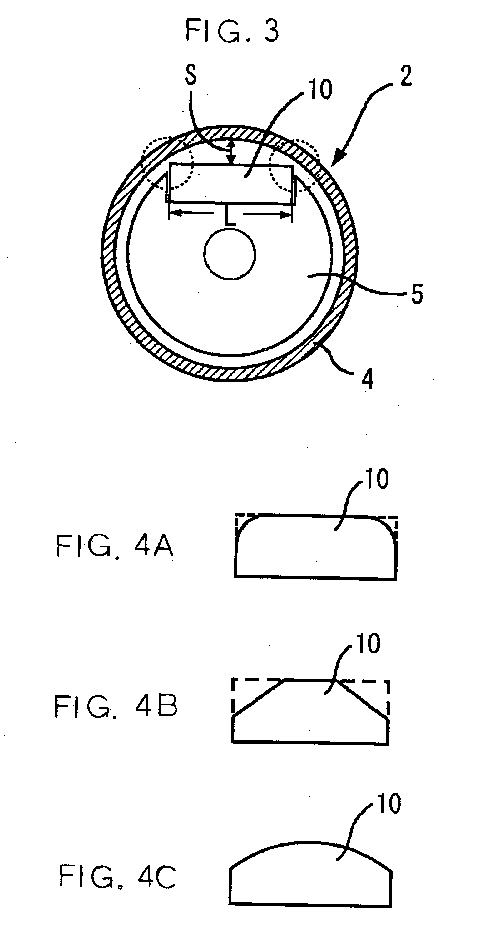
[0033] In FIG. 1, a developing roller 2 is provided to a developing apparatus 1, and the developing roller 2 is disposed across from a photosensitive drum (latent image support; not shown) via an opening 3 formed in the developing apparatus casing. The developing roller 2 is constituted by a developing sleeve 4, which comprises aluminum, brass, stainless steel, a conductive resin, or another such nonmagnetic material formed into a cylindrical shape, and a magnet roll 5 provided inside this developing sleeve 4. The developing sleeve 4 is rotated clockwise in the drawing by a drive means (not shown), while the magnet roll 5 is in a fixed state.

[0034] The magnet roll 5 has a diameter of approximately 23 mm, is composed of a rubber magnet or plastic magnet obtained by dispersing a magnetic powder in a polymer compound, and can be obtained by extrusion molding, for example. Spec...


PUM

PropertyMeasurementUnit
magnetic flux densityaaaaaaaaaa
widthaaaaaaaaaa

Abstract

A developing roller, comprising a developing sleeve consisting of a nonmagnetic material, and a magnet roll provided inside the developing sleeve and formed by dispersing a magnetic powder in a polymer compound, the portion corresponding to the developing pole of the magnet roll being equipped with a main-pole molded magnet whose magnetic force per unit of volume is greater than that of the magnet roll, wherein the magnetic pole adjacent to the developing pole of the magnet roll downstream in the developer conveyance direction has a peak magnetic flux density on the developing sleeve equal to or greater than that of the developing pole, and has a half value width, which is the width of the magnetic pole at which a magnetic flux density of one-half the peak magnetic flux density is exhibited, is greater than that of the developing pole.

Description

BACKGROUND OF THE INVENTION [0001] 1. Field of the Invention [0002] The present invention relates to a developing apparatus, to a developing apparatus in which the developing roller is used, and to a process cartridge and an image formation apparatus equipped with the developing apparatus. [0003] 2. Description of the Related Art [0004] With an electrophotographic image formation apparatus such as a copier, laser printer, or fax machine, or a multi-purpose machine combining two or more of these functions, an electrostatic latent image formed on a latent image support such as a photosensitive drum or photosensitive belt is developed by a developing apparatus to produce a visible image. A so-called two-component developing system, featuring a developer obtained by mixing a nonmagnetic toner with a magnetic carrier, is well known and has been widely used in such developing apparatus in recent years. [0005] With this two-component developing system, the developer is magnetically held to...

Claims


Application Information

Patent Timeline
Patent Type & Authority Applications(United States)
IPC IPC(8): F16C13/00G03G15/08G03G15/09H01F7/02
CPCG03G15/0921
Inventor KAKEGAWA, MIEKOKAMOI, SUMIOKOETSUKA, KYOHTAKAMIYA, NORIYUKIIMAMURA, TSUYOSHI
Owner RICOH KK
Why Eureka
Try Eureka