Radio relay device

a relay device and radio technology, applied in multiplex communication, synchronisation signal speed/phase control, synchronisation arrangement, etc., can solve the problems of enlarging circuit scale, communication cannot be done, conventional radio relay devices, etc., to prevent packet collisions and prevent packet transmission timings.

Inactive Publication Date: 2005-06-23
PANASONIC CORP
View PDF5 Cites 70 Cited by
  • Summary
  • Abstract
  • Description
  • Claims
  • Application Information

AI Technical Summary

Benefits of technology

[0029] In this configuration, in communication with the other electronic device serving as the slave, the relay apparatus can communicate with the other electronic device at the corrected timing so that the packet transmission / reception for the electronic device serving as the master and that for the other electronic device serving as the slave are executed at the timing synchronous with the clock of the electronic device serving as the master. Thus, it is possible to prevent the transmission timings of the packet from gradually shifting to the same timing, thereby preventing collision of packets. Further, in a simple configuration, synchronization of the packets can be taken so that the communicating procedure or circuit for changing the transmission timing using e.g. a control data is not required.

Problems solved by technology

Therefore, if a plurality of electronic devices simultaneously perform the communication, collision of the respective transmission data occurs so that the communication cannot be done.
However, the conventional radio relay device has the following disadvantage.
This leads to a problem of enlarging the circuit scale.
This complicates the communicating procedure.
In the case of the synchronous packet in the line switched system, since the communication is performed at prescribed slot intervals, changing the transmission / reception timing leads to deterioration in a data quality.
Further, the Bluetooth does not have the control data of changing the transmission / reception timing as a measure.
Thus, the radio relay device described in Patent Reference 1 cannot be applied to the radio network such as the Bluetooth.
Further, in the relay station disclosed in Patent Reference 2, since the packet is delayed by one slot for each of the plurality of relay stations, the delay of the packet increases with an increase in the number of the steps of the relay stations.

Method used


Image

  • Radio relay device
  • Radio relay device
  • Radio relay device

Examples


Embodiment Construction

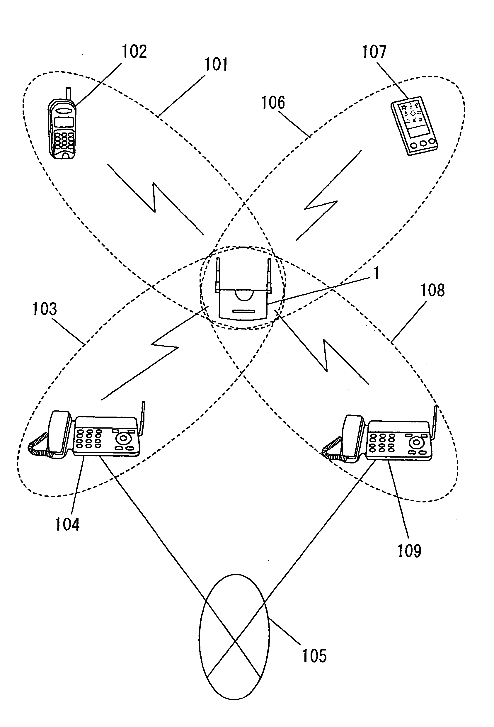
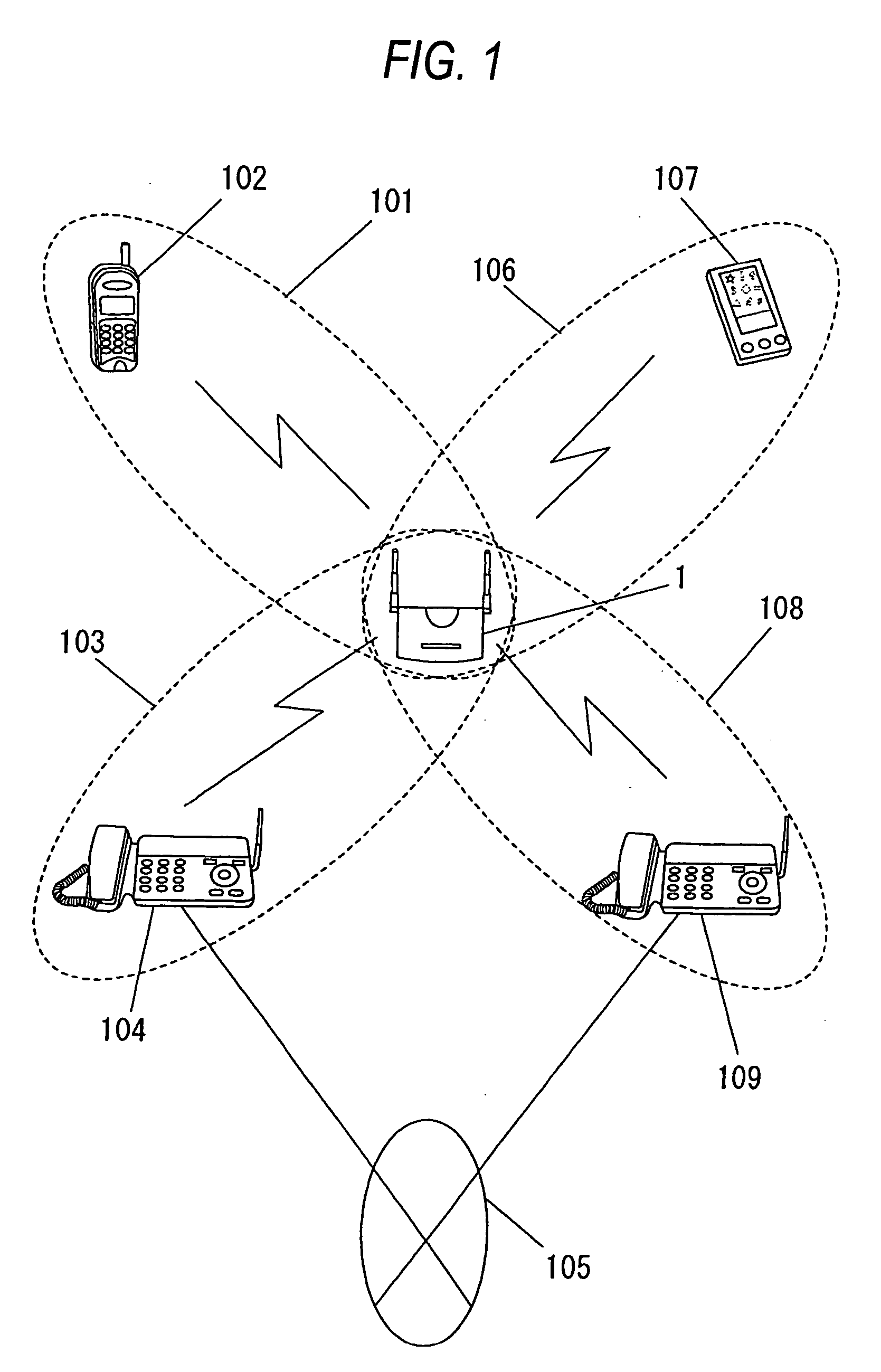
[0040] Now referring to the drawings, an explanation will be given of an embodiment of this invention. FIG. 1 is a view showing the configuration in which a repeater which is an example of the radio relay device according to an embodiment of this invention is connected to radio networks.

[0041] In the example shown in FIG. 1, a repeater 1 which is a radio relay device belongs to four radio networks, i.e. a first piconet 101, a second piconet 103, a third piconet 106 and a fourth piconet 108. In the first piconet 101 and third piconet 106, a repeater 1 serves as a master. In the second piconet 103, the repeater 1 serves as a slave and is connected to a parent device 104 serving as a master. In the fourth piconet 108, the repeater 1 serves as the slave and is connected to a parent device 109 serving as the master.

[0042] A child device 102 of the cordless telephone within the first piconet 101 as the radio network is connected to the parent device 104 of the cordless telephone through...


PUM


Abstract

This invention provides a radio relay device with a small size and reduced cost which can prevent collision of communication data when the communication data are relayed in a plurality of radio networks.
The radio relay device relays the communication data between a parent device and a child device of a cordless telephone. The radio relay device includes a synchronization timing detector 16 for detecting a synchronization timing with the transmission of the parent device when relaying a packet transmitted from the parent device to the child device of a different radio network (piconet) and a timing correcting value buffer 20 for storing a correcting value computed from a difference between the synchronization timing and a clock in a bit counter 19. When the radio relay device relays the packet from the parent device to the child device, it communicates with the child device at the timing corrected on the basis of the correcting value extracted from the timing correcting value buffer 20.

Description

BACKGROUND OF THE INVENTION [0001] 1. Field of the Invention[0002] This invention relates to a radio relay device capable of relaying a data communication, telephone call and communication data for printing in a master-slave type of radio network. [0003] 2. Description of the Related Art [0004] In recent years, various standards of the radio network have been specified, and the radio network is connected to another radio network in the same standard having various uses. [0005] For example, as regards the Bluetooth (trademark) in the radio network standard, not only a computer but also a computer peripheral device such as a printer and scanner and an electronic device such as a facsimile device, audio device and cordless telephone can be connected to one another in the Bluetooth standard. Thus, the respective electronic devices are adapted to transmit / receive information, sound, and images. [0006] In the Bluetooth, within a piconet which is the radio network, an electronic device whi...

Claims


Application Information

Patent Timeline
Patent Type & Authority Applications(United States)
IPC IPC(8): H04L12/28H04B7/155H04B7/26H04J3/06H04L7/04H04W16/26H04W56/00H04W84/12H04W84/20H04W88/04
CPCH04B7/155H04B7/2681H04J3/0685H04W88/04H04W28/04H04W56/00H04L7/04
Inventor SUWA, YUTAKA
Owner PANASONIC CORP
Why Eureka
Try Eureka