Reducing local oscillation leakage in a radio frequency transmitter

a radio frequency transmitter and local oscillation technology, applied in the field of wireless communication systems, can solve the problems of adversely affecting the recapturing of data, data cannot be accurately extracted from the rf signal, lo leakage, etc., and achieve the effect of reducing lo leakage and signal strength reduction

Active Publication Date: 2005-06-23
VIXS SYSTEMS INC
View PDF9 Cites 5 Cited by
  • Summary
  • Abstract
  • Description
  • Claims
  • Application Information

AI Technical Summary

Benefits of technology

[0009] The reduced LO leakage of a radio frequency transmitter of the present invention substantially meets these needs and others. In one embodiment, a method for reducing LO leakage in a radio frequency transmitter begins by producing analog outbound signals from digital outbound signals that represent transmit data. The processing continues by amplifying the analog outbound signals to produce amplified analog outbound signals. The process then continues by mix

Problems solved by technology

The LO leakage results due to mismatches in the components of the in-phase and quadrature mixers of the first IF mixer as well as mismatches between the in-phase intermediate frequency and quadrature intermediate local oscillation.
As is known, when an RF signal that includes an LO leakage

Method used


Image

  • Reducing local oscillation leakage in a radio frequency transmitter
  • Reducing local oscillation leakage in a radio frequency transmitter
  • Reducing local oscillation leakage in a radio frequency transmitter

Examples


Embodiment Construction

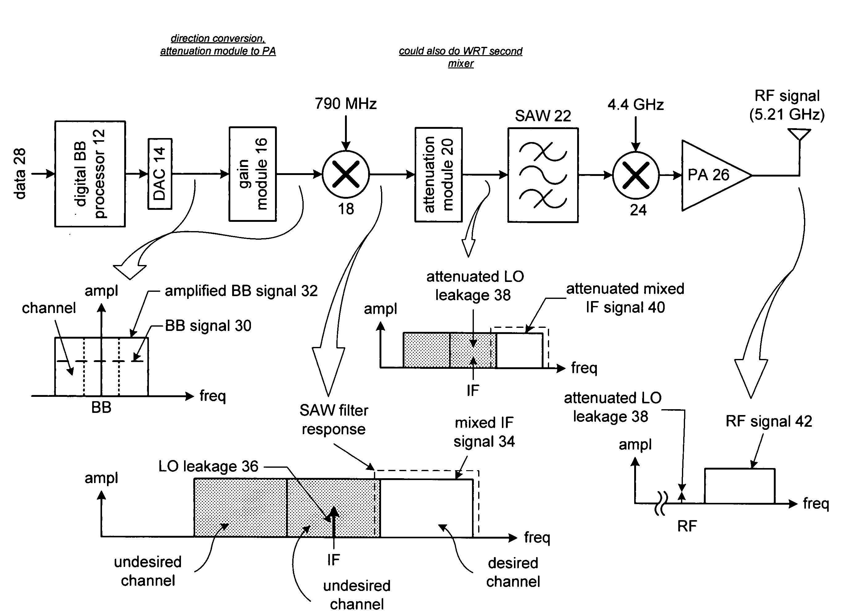
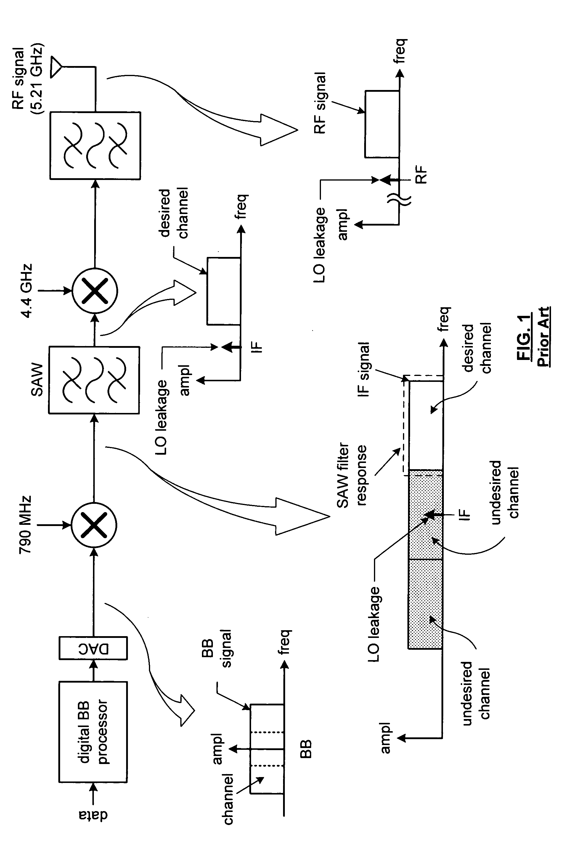
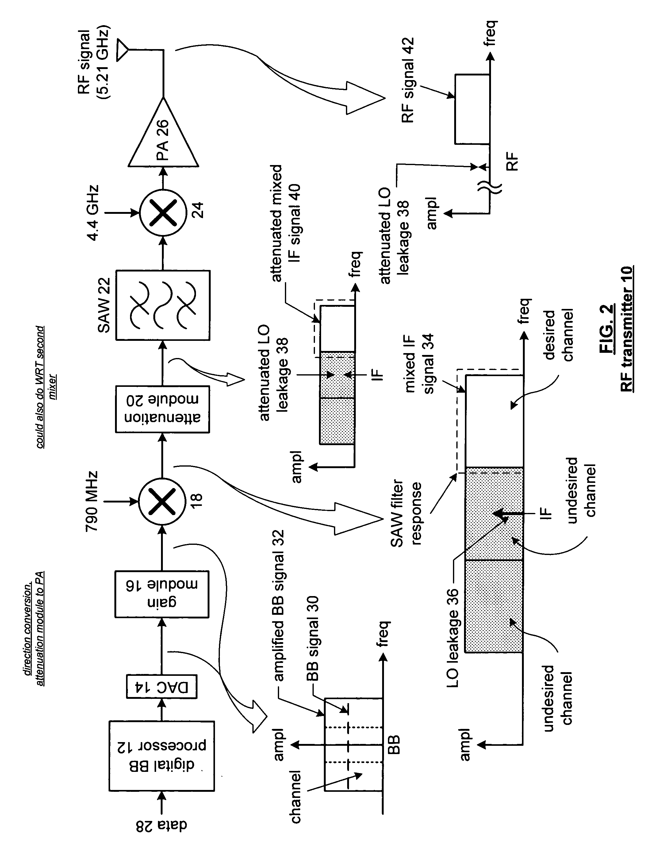
[0015]FIG. 2 is a schematic block diagram of a radio frequency (RF) transmitter 10 that includes a digital baseband processor 12, a digital-to-analog converter 14, a gain module 16, a 1st mixing stage 18, an attenuation module 20, a surface acoustic wave (SAW) filter 22, a 2nd mixing stage 24, and a power amplifier 26. The digital baseband processor 12 is operably coupled to encode data 28 based on an encoding protocol as prescribed by one or more standards being supported by the RF transmitter 10. Such standards include, but are not limited to, IEEE 802.11a, IEEE 802.11b, IEEE 802.11g, Bluetooth, et cetera. The encoding includes, but is not limited to, forward error correction, interleaving, mapping, et cetera. The resulting digital baseband signal is then converted to an analog baseband signal via the digital-to-analog converter 14. Note that, as shown, the analog baseband signal 30 is a complex signal (i.e., includes an in-phase component and a quadrature component), which requir...


PUM


Abstract

A method for reducing LO leakage in a radio frequency transmitter begins by producing analog outbound signals from digital outbound signals that represent transmit data. The processing continues by amplifying the analog outbound signals to produce amplified analog outbound signals. The process then continues by mixing the amplified analog outbound signals with a local oscillation to produce mixed signals having an LO leakage component. The processing then continues by attenuating the mixed signals having the LO leakage component to produce mixed signals having reduced LO leakage.

Description

BACKGROUND OF THE INVENTION [0001] 1. Technical Field of the Invention [0002] This invention relates generally to wireless communication systems and more particularly to radio frequency transmitters used within such systems. [0003] 2. Description of Related Art [0004]FIG. 1 is a schematic block diagram of a known super heterodyne radio frequency transmitter architecture. As shown, the transmitter includes a digital baseband (BB) processor, a digital-to-analog converter (DAC), a 1st intermediate frequency mixer, a surface acoustic wave (SAW) filter, a 2nd intermediate frequency mixer, a bandpass filter, a power amplifier (not shown) and an antenna. In operation, the digital baseband processor converts data into digital baseband signals in accordance with a particular encoding protocol as may be prescribed in various standards such as IEEE 802.11, Bluetooth, global system for mobile communications (GSM), et cetera. The digital-to-analog converter converts the baseband digital signal i...

Claims


Application Information

Patent Timeline
IPC IPC(8): H03C1/62H04B1/04H04B17/00
CPCH04B1/0475
Inventor SUBASIC, BOJANRYBICKI, MATHEW A.
Owner VIXS SYSTEMS INC
Why Eureka
Try Eureka