
Optical communication equipment and vehicle control method

a communication equipment and optical technology, applied in the direction of vehicle position/course/altitude control, process and machine control, instruments, etc., can solve the problems of inapplicability to a place, difficult to control the traveling of only a specific, and inability to control the system in large-scale, etc., to achieve reliable supply, simple overall configuration, and effective utilization of optical properties

Inactive Publication Date: 2005-06-23
SONY CORP
View PDF7 Cites 62 Cited by
  • Summary
  • Abstract
  • Description
  • Claims
  • Application Information

AI Technical Summary

Benefits of technology

The present invention proposes a novel optical communication system and a novel vehicle control method that ensures for easy and reliable traveling of a vehicle in a complicated area where multiple roads intersect. The system includes optical communication equipment installed in the vehicle for transmitting and receiving various information to and from similar equipment installed in another vehicle via optical communication. The optical communication equipment transmits information of traffic regulations to be received by the inter-vehicle communication equipment. The vehicle control method comprises notifying information of traffic regulations to the vehicle and controlling the vehicle's traveling accordingly. The invention simplifies the overall configuration of the system and ensures reliable supply of specific information of traffic regulations even in an urban city or the like where multiple roads intersect.

Problems solved by technology

According to these methods, however, there are such problems that because dedicated facilities must be installed along the road and installed in a vehicle, its system inevitably becomes large-scaled.
Further, because it depends on data transmission by radio, even if a frequency band having strong directivity is employed, it is difficult to control the traveling of only a specific vehicle traveling in a specific area, thereby it is not applicable to a place where a plurality of roads intersect in complication such as in urban cities or the like.

Method used


Image

  • Optical communication equipment and vehicle control method
  • Optical communication equipment and vehicle control method
  • Optical communication equipment and vehicle control method

Examples


Embodiment Construction

[0018] By referring to the accompanying drawings, preferred embodiments of the present invention will be described in detail.

(1) Configuration of Embodiment 1

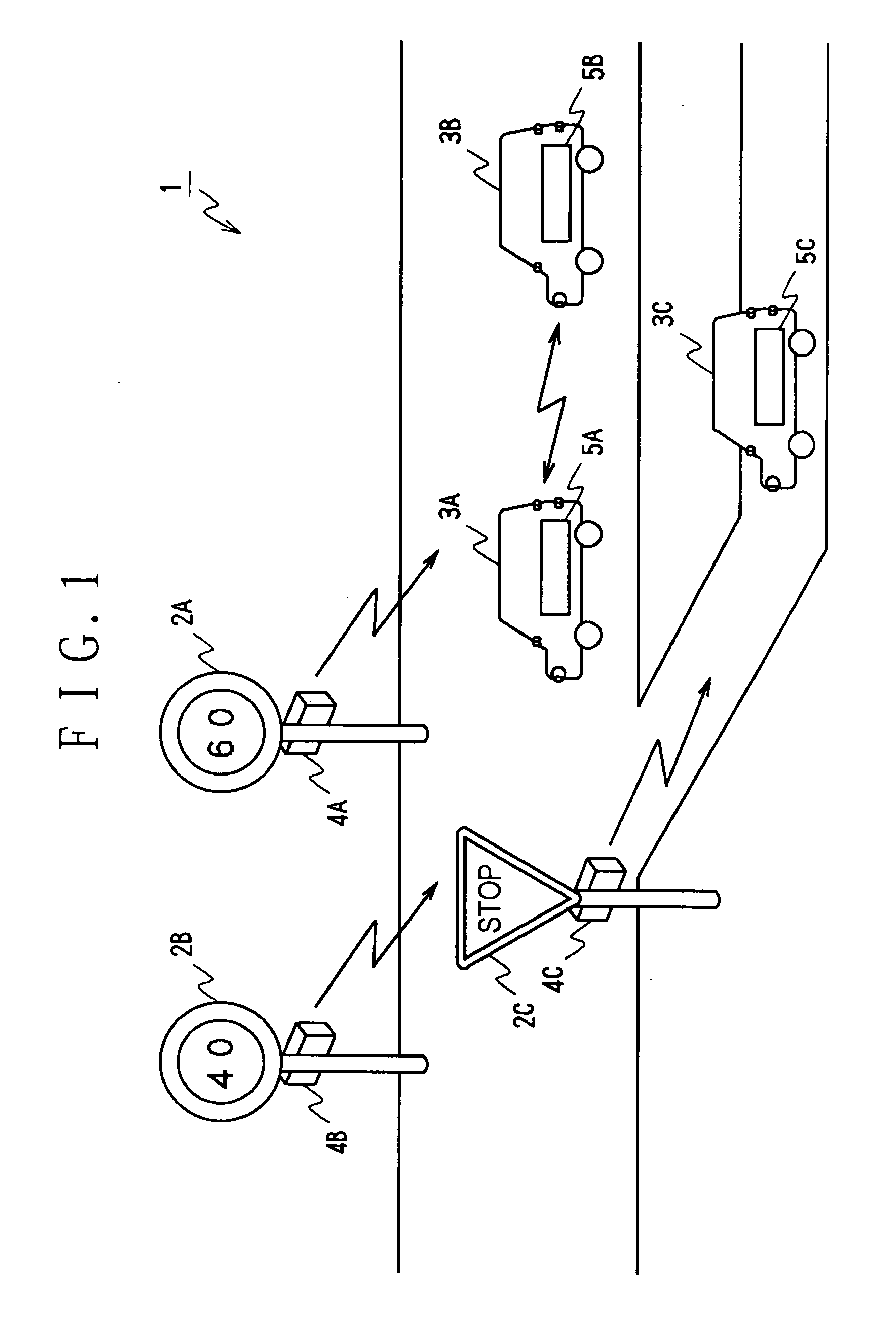
[0019]FIG. 1 is a block diagram showing a traffic control system according to the embodiment of the present invention. This traffic control system 1 enables controlling of vehicles 3A, 3B and 3C traveling on respective roads by means of optical communication equipment installed in a road sign such as road signs 2A, 2B indicating a maximum speed limit, and 2C indicating a stop sign or the like. According to this traffic control system 1, for controlling of the vehicles 3A to 3C by use of these road signs 2A to 2C, an inter-vehicle communication system based on optical communication is utilized by the vehicles 3A to 3C, thereby enabling to control the traveling of vehicles easily and reliably even in such a place where a plurality of roads intersect in complication.

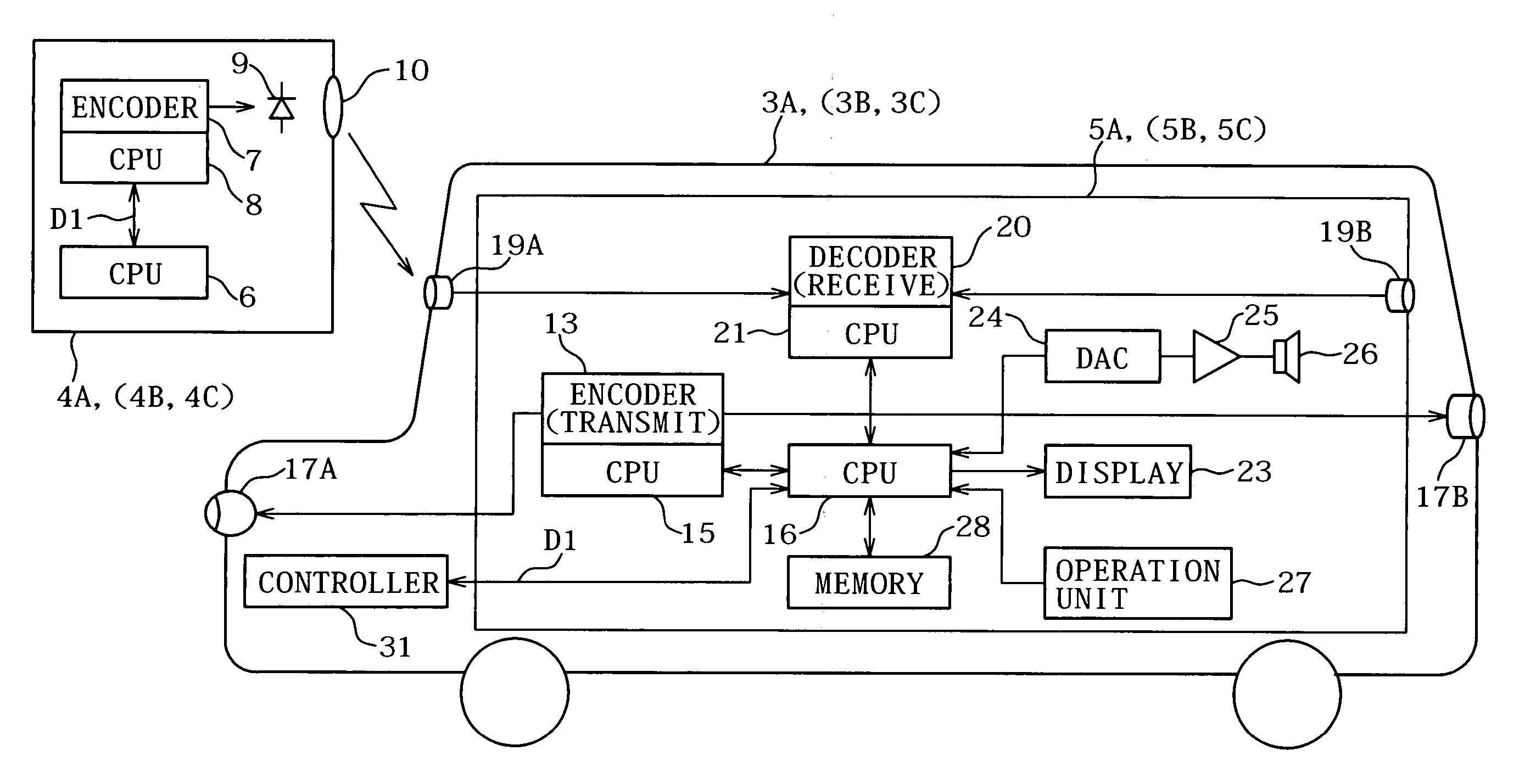
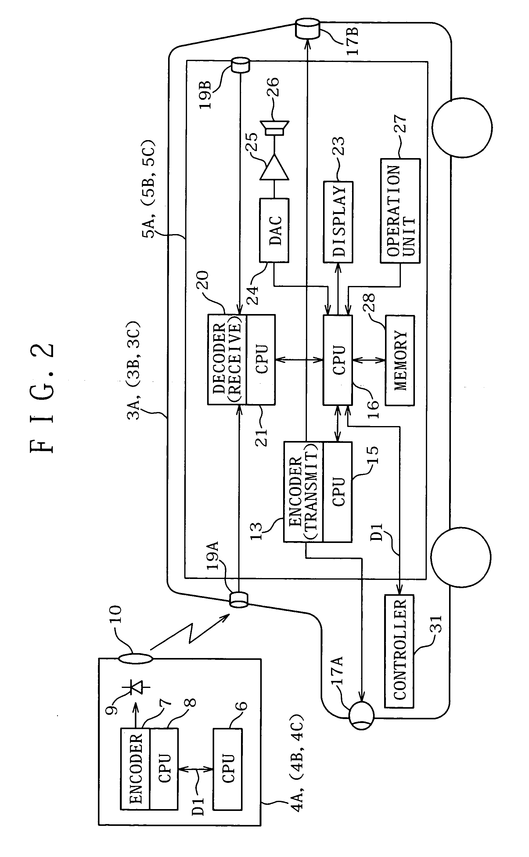
[0020]FIG. 2 is a block diagram showing optical communication...


PUM


Abstract

The present invention relates to optical communication equipment and a vehicle control method, and in particular, the present invention is applied to a system utilizing inter-vehicle communication equipment via optical communication to notify information of traffic regulation utilizing optical communication according to an inter-vehicle communication system so that traveling of a vehicle can be controlled easily and reliably even in such a complicated place where a plurality of roads intersect as in urban cities or the like.

Description

CROSS REFERENCES TO RELATED APPLICATIONS [0001] The present document is based on Japanese Priority Document JP 2003-419339, filed in the Japanese Patent Office on Dec. 17, 2003, the entire contents of which being incorporated herein by reference. BACKGROUND OF THE INVENTION [0002] 1. Field of the Invention [0003] The present invention relates to optical communication equipment and a vehicle control method, and in particular, it relates to a system utilizing inter-vehicle communication equipment via optical communication. By arranging to notify information of traffic regulations utilizing optical communication according to the inter-vehicle communication system, it is enabled by the present invention to control traveling of a vehicle easily and reliably even in such a complicated place where a plurality of roads intersect as in urban cities or the like. [0004] 2. Description of Related Art [0005] Conventionally, as a method for improving a safety driving of a vehicle, for example, Ja...

Claims


Application Information

Patent Timeline
Patent Type & Authority Applications(United States)
IPC IPC(8): G08C23/04B60Q1/26G08G1/09G08G1/0965G08G1/0967H04B10/11H04B10/116
CPCG08G1/0965G08G1/096725H04B10/1125G08G1/096783G08G1/096791G08G1/09675
Inventor SHINADA, AKIRA
Owner SONY CORP
Learn More