In-place data transformation for fault-tolerant disk storage systems

a disk storage system and data transformation technology, applied in the field of disk storage systems, can solve the problems of increasing the cost of the system, large databases, and persistent storage of huge amounts of data on physical disks, and achieve the effects of reducing the impact of performance on users, reducing the number of times, and reducing the amount of tim

Inactive Publication Date: 2005-06-23
AVAGO TECH INT SALES PTE LTD
View PDF17 Cites 50 Cited by
  • Summary
  • Abstract
  • Description
  • Claims
  • Application Information

AI Technical Summary

Benefits of technology

[0013] Another objective of the present invention is to perform RAID level migration without causing any reduction in fault tolerance.
[0014] Another objective of the present invention is perform RAID level migration while minimizing the performance impact on users who are accessing the array while the RAID level migration takes place.
[0015] Another objective of the present invention is to perform RAID level migration in a shorter amount of time than RAID level migration schemes that require copying of data to a temporary storage area.
[0016] In accordance with the invention, the data are transformed in a most optimal manner with a single copy operation while user concurrently access the data, without a reduction in fault-tolerance and with less of a performance impact.

Problems solved by technology

Modern computer systems can persistently store huge amounts of data on physical disks.
This is inevitable, and a problem because most prior art systems require extra disks to store copies of the data during the transformation so that should a fault occur, the data can be recovered.
This increases the cost of the system.
There are other problems with large databases.
The performance of disk devices is limited by physical constraints, such as the speed at which disks can rotate, and heads can move.
Clearly, transforming large amounts of data stored on many disks is a costly and time-consuming process.
This meant that no user data transfers were permitted during the transformation.
In a global data processing environment, where access is frequently by the Internet, and can happen at any time, scheduled “down-time” is intolerable.
Using the temporary storage area for ORLM has at least two extremely large performance problems.
The constant movement of the heads between the tracks used for the temporary storage area and the tracks used for the user data causes a noticeable degradation in performance.
Consequently, such an OLRM strategy is bad, not only is the user subjected to degraded performance, but also the degraded performance can last for hours, if not days.

Method used


Image

  • In-place data transformation for fault-tolerant disk storage systems
  • In-place data transformation for fault-tolerant disk storage systems
  • In-place data transformation for fault-tolerant disk storage systems

Examples


Embodiment Construction

[0025] Basic Goals of In-Place Fault Tolerant Data Transformation

[0026] On-line RAID level migration transforms data from any starting RAID level (0, 1, 2, 3, 4, 5, 10, or 50) to any other RAID level (0, 1, 2, 3, 4, 5, 10, or 50) without taking the RAID system off-line. Although the present invention is described in terms of OLRM from RAID-5 set to RAID-10, it should be understood that the system and method described herein can be used to transform any type of data stored on disks.

[0027] ORLM Mapping for Multiple Disks

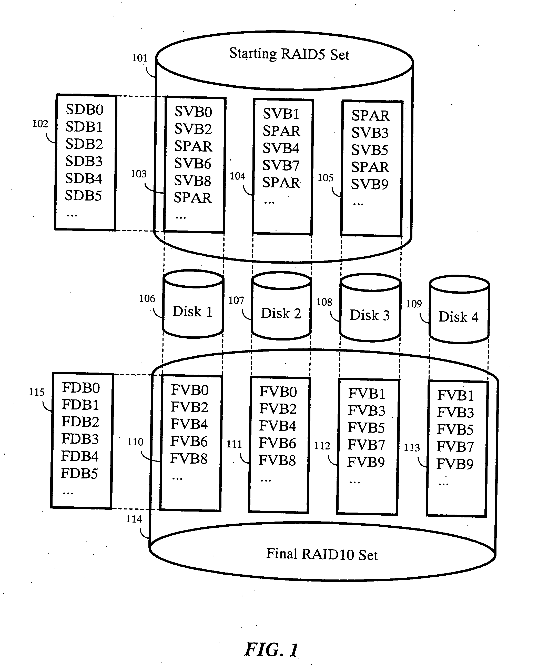
[0028]FIG. 1 shows the structure a set of disks 106-109 used to transform the starting RAID-5 set 101 to the final RAID-10 set 114 according to our invention. For the starting RAID set 101, the transformation uses the same starting data blocks (SDB) 102 on each of the disks 106-108.

[0029] The FIG. 1 also shows a start virtual block (SVB) and parity (SPAR) mapping 103-105. SVB0 is mapped to Disk1106, SDB0; SVB1 is mapped to Disk2107, SDB0; a parity block (SPAR), for...


PUM


Abstract

A fault tolerant method transforms physically contiguous data in-place on a disk by partitioning the physically contiguous data into an empty region physically adjacent to data regions including a first data region and a last data region, the first and last data regions at opposing ends of the physically contiguous data regions. The physically contiguous data are transformed in an order beginning with the first data region and ending with the last data region. The transforming step perform first locking and reading the first data region, second, transforming the first data region, third, writing and unlocking the transformed first data region to the empty region, and fourth, declaring the first data region as the empty region while declaring the empty region as the first region. The first through fourth steps are repeated for each data region, until completion, to transform the physically contiguous data in-place on the disk.

Description

FIELD OF THE INVENTION [0001] This invention relates generally to the field of disk storage systems, and more particularly to transforming data between various disk storage data formats. BACKGROUND OF THE INVENTION [0002] Modern computer systems can persistently store huge amounts of data on physical disks. It is not unusual for a single disk to store gigabytes of data, and large systems can have hundreds, if not thousands of disks. Users of these systems demand continuous, fault-tolerant access to the data. However, from time to time as systems expand and modernize, it is necessary to transform the data to a different format. This is inevitable, and a problem because most prior art systems require extra disks to store copies of the data during the transformation so that should a fault occur, the data can be recovered. This increases the cost of the system. [0003] There are other problems with large databases. The performance of disk devices is limited by physical constraints, such ...

Claims


Application Information

Patent Timeline
Patent Type & Authority Applications(United States)
IPC IPC(8): G06F11/00G06F13/00H04B1/74
CPCG06F3/061G06F3/0638G06F2211/1004G06F11/1092G06F3/0689
Inventor FRANKLIN, CHRIS R.WONG, JEFFREY T.
Owner AVAGO TECH INT SALES PTE LTD
Why Eureka
Try Eureka